go back to ACADEMICS pagego back to ACADEMICS page
components of LEARNING ELEMENTS group 1go back to ACADEMICS page
components of LEARNING ELEMENTS group 2PS 141 ANNOUNCEMENT page
components of LEARNING ELEMENTS group 3
components of LEARNING ELEMENTS group 4PS 141 ANNOUNCEMENT page
components of LEARNING ELEMENTS group 5
components of LEARNING ELEMENTS group 6
components of LEARNING ELEMENTS group 7


PS 141 (CS) Electronics for
Computer Science Sophomores


PS 141 Site Structure   and   Course Block Diagram


1 - who are 1's and 0's anyway?
      laboratory report on learning elements


T O P         NEXT         PREVIOUS


2 - counting up and down
      laboratory report on learning elements
    ( christmas lights with 7442 / 7490 / 7493 / 74193 / 7442 / 7447 )
 

T O P         NEXT         PREVIOUS


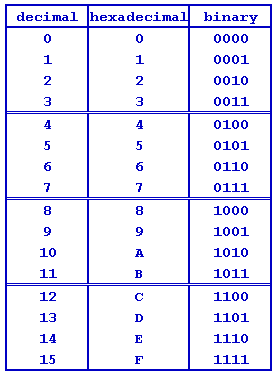
counting - hardware style

  • decimal "1" to "10"


  • binary "0" to "1111"


  • hexadecimal "0" to "F"


3 - making decisions (logic gates / selectors / multiplexer / demultiplexer)
      laboratory report on learning elements


T O P         NEXT         PREVIOUS


4 - analog switches (diodes / transistors / operational amplifiers)
      laboratory report on learning elements


T O P         NEXT         PREVIOUS

ON/OFF switches, AND / NAND / OR / NOR gates
 

5 - op-amp analog applications
      laboratory report on learning elements


T O P         NEXT         PREVIOUS

  • basics of an operational amplifier.

      click for OpAmp Basics


  • Exercise 5. Build an OpAmp circuit to comply with the specifications below.

    1. Power supply : +12 volts, -12 volts, GND (0 volt).


    2. Connections according to the circuit above.


    3. R(f) + R(i) = 500K. Use a 500K potentiometer to perform the role of a volume control.


    4. Generate a "sine wave" using a "Signal Generator" and introduce 50-millivolts between the NInv (connected to GND) and Inv.


    5. Connect "Channel A" of the oscilloscope to the Inv input and "Channel B" to the "output" of the OpAmp.


    6. Manipulate the "volume control" and watch the behavior of signals shown in channel A and channel B.


6 - transistor analog applications
      laboratory report on learning elements


T O P         NEXT         PREVIOUS


7 - allocated for specific interests
      laboratory report on learning elements


T O P         NEXT         PREVIOUS

    did you know you could build a digital voltmeter without using computers or microprocessors? you could use only TTL and analog devices using the so-called "successive approximation" method