|
1
|
this is a very simple circuit and is very much related to the one described for the 555, earlier.
|
| 2
|
principle of operation :
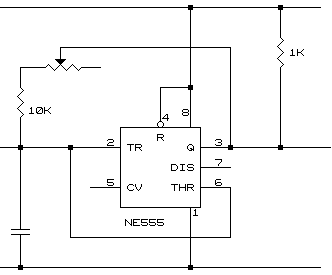
- the 555 is configured as a variable frequency oscillator.
- the resistive and capacitive circuit parameters are chosen to provide audio frequency.
- sound may be picked up from pins 3 or 7, as the designer so chooses.
- a simple audio driver is provide in another circuit.
go to top next
|
|
|
| 3
|
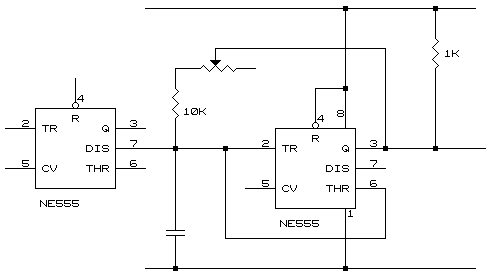
principle of operation :
- the input to the variable frequency generator above is one that prevents oscillation.
- this function can be done many ways,
- bring pin #4 (the reset pin of the 555) to ground
- provide a diode to clamp the capacitor voltage low or high
- provide an npn transistor whose collector is at the positive terminal of the capacitor to discharge it or allow it to charge
- provide a diode with its anode at the positive terminal of the capacitor also discharging it or allowing it to charge
- provide another 555 with its pin #7 (open collector output) at the positive terminal of the capacitor also discharging it or allowing it to charge
go to top prev
|
|
|
| 4
|
in summary, sound which crosses the threshold of the amplifier produces the op-amp to latch high. this level must be sensed by another circuit as a pre-determined signal to implement an action.
|