|
1
|
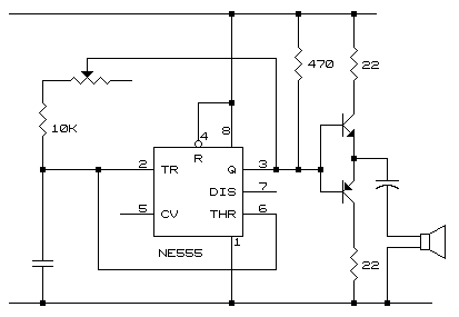
this simple circuit illustrates the use of an npn transistor and a pnp transistor to alternately provide the required power drive to the speaker, through a capacitive coupling.
|
| 2
|
principle of operation :
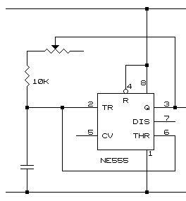
- the 555 is configured as a variable frequency oscillator.
- it provides the sound of the proper voltage to a current amplifier, described below.
go to top next
|

|
|
| 3
|
principle of operation :
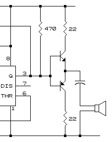
- sound can come from any source.
- if it does not have the required voltage, then, it should first pass through a voltage amplifier for that purpose.
- if it does, then that output is fed to the base of an npn to provide a positive current drive to the speaker,
- or a negative current drive through the pnp.
- the size of the capacitor and the two 22-ohm resistors connected to their respective collector terminals, provide the overload current protection to the speaker and the two transistors.
- since the input is a fast rising and a fast falling edge, the capacitor presents a low impedance to the circuit, such that its value is almost zero.
- the 22-ohm resistors limit the maximum current to the speaker and to the collector of each of the transistors to below 200 milliamps.
go to top prev
|

|
|
| 4
|
this driver circuit cannot be used for "high-fidelity" applications because it has a voltage blind band (area without a corresponding response) of about 1.2 volts.
|

