TOP
Some light dimmer history
Light dimming is based on adjusting the voltage which gets to the lamp. Light dimming has been possible for many decades by using adjustable power resistors and adjustable transformers. Those methods have been used in movie theatres, stages and other public places. The problem of those light controlling methods have been that they are big, expensive, have poor efficiency and they are hard to control from remote location.
The power electronics have proceeded quickly since 1960. Between 1960-1970 thyristors and triacs came to market. Using those components it was quite easy to make small and inexpensive light dimmers which have good efficiency. Electronics controlling also made possible to make them easily controllable from remote location. This type of electronic light dimmers became available after 1970 and are nowadays used in very many locations like homes, restaurants, conference rooms and in stage lighting.
TOP
How modern light dimmers work ?
Solid-state light dimmers work by varying the "duty cycle" (on/off time) of the full AC voltage that is applied to the lights being controlled. For example, if the voltage is applied for only half of each AC cycle, the light bulb will appear to be much less bright than when it get the full AC voltage, because it get's less power to heat the filament. Solid-state dimmers use the brightness knob setting to determine at what point in each voltage cycle to switch the light on and off.
Typical light dimmers are built using thyristors and the exact time when the thyristor is triggered relative to the zero crossings of the AC power is used to determine the power level. When the the thyristor is triggered it keeps conducting until the current passing though it goes to zero (exactly at the next zero crossing if the load is purely resistive, like light bulb). By changing the phase at which you trigger the triac you change the duty cycle and therefore the brightness of the light.
Here is an example of normal AC power you get from the receptacle (the picture should look like sine wave):

As you can see, by varying the turn-on point, the amount of power getting to the bulb is adjustable, and hence the light output can be controlled.
The advantage of thyristors over simple variable resistors is that they (ideally) dissipate very little power as they are either fully on or fully off. Typically thyristor causes voltage drop of 1-1.5 V when it passes the load current.
TOP
Circuit Components
thyristors and triacs
A Silicon Controlled Rectifier is one type of thyristor used where the power to be controlled is unidirectional. The Triac is a thyristor used where AC power is to be controlled.
Both types are normally off but may be triggered on by a low current pulse to an input called the gate. Once triggered on, they remain on until the current flowing through the main terminals of the device goes to zero.
Both SCRs and Triacs are 4 layer PNPN structures. The usual way an SCR is described is with an analogy to a pair of cross connected transistors - one is NPN and the other is PNP.
                   +------+
    + >------------+ LOAD +----------------+
                   +------+                |
                                           |
                                          E \|
                                      PNP    |---+-------< IG(-)
                                          C /|   |
                                           |     |
                                           |   |/ C
                         Gate IG(+)  >-----+---|    NPN
                                               |\ E
                                                 |
                                                 |
    - >------------------------------------------+
If we connect the positive terminal of a supply to say, a light bulb, and then to the emitter of the PNP transistor and its return to the emitter of the NPN transistor, no current will flow as long as the breakdown voltage ratings of the transistor are not exceeded because there is no base current to either.
However, if we provide some current to the base of the NPN (IG(+)) transistor, it will turn on and provide current to the base of the PNP transistor which will turn on providing more current to the NPN transistor. The entire structure is now in the on state and will stay that way even when the input to the NPN's base is removed until the power supply goes to 0 and the load current goes to 0.
The same scenario is true if we reverse the power supply and use the IG(-) input for the trigger.
A Triac works basically in a similar manner but the polarity of the Gate can be either + or - during either half cycle of an AC source. Typically the trigger signals used for triggering triacs are short pulses.
TOP
555 Timer
The 555 is made out of simple transistors that are about the same as on / off switches. They do not have any sense of time. When you apply a voltage they turn on and when you take away the voltage they turn off. So by itself, the 555 can not create a pulse. The way the pulse is created is by using some components in a circuit attached to the 555. This circuit is made of a capacitor and a resistor. We can flip a switch and start charging the capacitor. The resistor is used to control how fast the capacitor charges. The bigger the resistance, the longer it takes to charge the capacitor. The voltage in the capacitor can then be used as an input to another switch. Since the voltage starts at 0, nothing happens to the second switch. But eventually the capacitor will charge up to some point where the second switch comes on.
The way the 555 timer works is that when you flip the first switch, the output pin goes to Vcc (the supply voltage) and starts charging a capacitor. When the capacitor voltage gets to 2/3 Vcc (Vcc * 2/3) the second switch turns on which makes the output go to 0 volts.

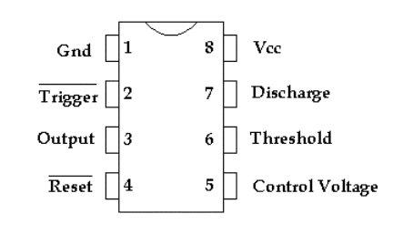
Pin 2 (Trigger) is the 'on' switch for the pulse. The line over the word Trigger tells us that the voltage levels are the opposite of what you would normally expect. To turn the switch on you apply 0 volts to pin 2. The technical term for this opposite behavior is 'Active Low'.
Pin 6 is the off switch for the pulse. We connect the positive side of the capacitor to this pin and the negative side of the capacitor to ground. When Pin 2 (Trigger) is at Vcc, the 555 holds Pin 7 at 0 volts (Note the inverted voltage). When Pin 2 goes to 0 volts, the 555 stops holding Pin 7 at 0 volts. Then the capacitor starts charging. The capacitor is charged through a resistor connected to Vcc. The current starts flowing into the capacitor, and the voltage in the capacitor starts to increase.
Pin 3 is the output (where the actual pulse comes out). The voltage on this pin starts at 0 volts. When 0 volts is applied to the trigger (Pin 2), the 555 puts out Vcc on Pin 3 and holds it at Vcc until Pin 6 reaches 2/3 of Vcc (Vcc*2/3). Then the 555 pulls the voltage at Pin 3 to ground and you have created a pulse. (Again notice the inverting action.) The voltage on Pin 7 is also pulled to ground, connecting the capacitor to ground and discharging it.
TOP
Incandescent lamp physics
A typical incandescent lamp take power and uses it to heat up a filament until it will start to radiate light. In the process about 10% of the energy is converted to visible light. When the lamp is first turned on, the resistance of the cold filament can be 29 times lower than it's warm resistance. This characteristic is good in terms of quick warmup times, but it means that even 20 times the steady-state current will be drawn for the first few milliseconds of operation. Lamp manufacturers quote a typical figure for cold lamp resistance of 1/17 th of the operational resistance, although inrush currents are generally only ten times the operational current when such things as cable and supply impedance are taken into account. The semiconductors, wiring, and fusing of the dimmer must be designed with this inrush current in mind. The inrush current characteristic of incandescent (tungsten filament) lamps is somewhat similar to the surge characteristic of the typical thyristors made for power controlling, making them a quite good match. The typical ten times steady state ratings which apply to both from a cold start allow many triacs to switch lamps with current ratings close to their own steady state ratings.
Because lamp filament has a finite mass, it take some time (depending on lamp size) to reach the operating temperature and give full light output. This delay is perceived as a "lag", and limits how quickly effect lighting can be dimmed up. In theatrical application those problems are reduced using preheat (small current flows through lamp to keep it warm when it is dimmed out).
The ideal lamp would produce 50% light output at 50% power input. Unfortunately, incandescents aren't even close that. Most require at least 15% power to come on at all, and afterwards increase in intensity at an exponential rate.
To make thing even more complicated, the human eye perceives light intensity as a sort of inverse-log curve. The relation of the the phase control value (triac turn on delay after zero cross) and the power applied to the light bulb is very non-linear. To get around those problems, most theatrical light dimmer manufacturers incorporate proprietary intensity curves in their control circuits to attempt to make selected intensity more closely approximate perceived intensity.
TOP
Circuit Flow

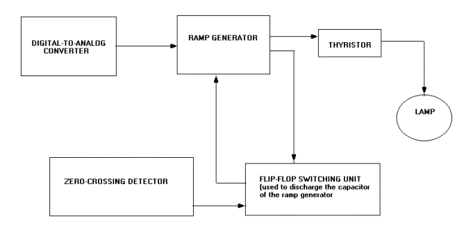
Three 555 Timers will be used to control the firing of the thyristor. The first task is to construct the ramp generator. The ramp generator is the circuit below minus the zero crossing detector and the flip-flop switching unit. For purposes of testing, a potentiometer connected to a 12 V supply, instead of the digital-to-analog converter is attached to the circuit. By adjusting the potentiometer, we are controlling the rate at which the capacitor attached to the leftmost 555 chip charges. Thus, the output of the first 555 is a ramp and its slope can be controlled using the potentiometer.
The zero-crossing on the other hand is connected to a 220/12V transformer. The zero-crossing detector outputs a pulse every time the input voltage crosses the zero volt mark. This output is one of the inputs fed into the flip-flop switch. This switch controls the charging and discharging of the capacitor in the ramp generator.
|