The Set Point and LDR Feedback
Concepts
P-I-D (proportional-integral-derivative) is an effective control system for continuous processes that performs two control tasks. First, P-I-D control keeps the output at a set level even though varying process parameters may tend to cause the output to vary from the desired set point. Second, P-I-D promptly and accurately changes the process level from one set point level to another set point level.
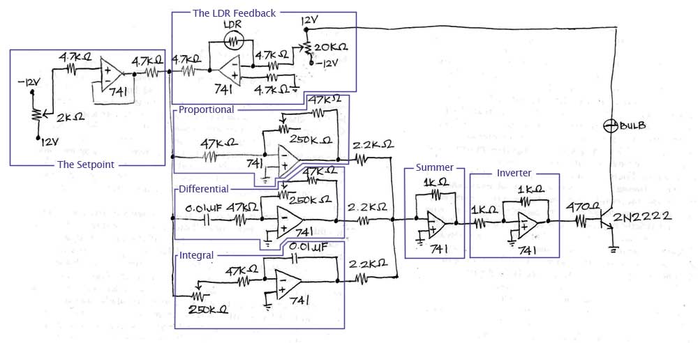
The set point is the target value that the P-I-D controller or an automatic control system, will aim to reach. The set point for this case is the state which dictates whether the bulb should turn on or off depending on the intensity of the light which in this circuit is implemented using a voltage follower as shown in the figure below.
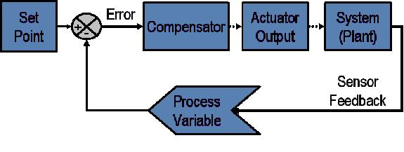
Figure 4: Set Point and LDR FeedbackIn a typical control system, the process variable is the system parameter that needs to be controlled, such as temperature (ºC), pressure (psi), or flow rate (liters/minute). A sensor is used to measure the process variable and provide feedback to the control system. The set point is the desired or command value for the process variable, such as 100 degrees Celsius in the case of a temperature control system. At any given moment, the difference between the process variable and the set point is used by the control system algorithm (compensator), to determine the desired actuator output to drive the system (plant). For instance, if the measured temperature process variable is 100 ºC and the desired temperature set point is 120 ºC, then the actuator output specified by the control algorithm might be to drive a heater. Driving an actuator to turn on a heater causes the system to become warmer, and results in an increase in the temperature process variable. This is called a closed loop control system, because the process of reading sensors to provide constant feedback and calculating the desired actuator output is repeated continuously and at a fixed loop rate as illustrated in the figure below.
Figure 5: Closed Loop Control System
The set point configuration is constructed by simply connecting an output of an operation amplifier to its inverting input and using the non-inverting for the signal input. It would basically copy the set input voltage at the output of the voltage follower with a gain depending on the resistors. Such configuration does not draw any current from the input thus it would not greatly affect the operation of the controller or of the circuit in general. Likewise, the set point or the output voltage would easily be adjusted by varying the value of the resistors.
The sensor on the other hand is implemented with a light dependent resistor wherein its resistance decreases as the intensity of light increases. The value of resistance determines the amount of voltage that would be stored in the LDR, and so as the output of the sensor circuit.
In adjusting the two potentiometers in the set point-LDR part of the circuit, we should make sure that the polarities of the output voltage of the potentiometers in the diagram are the same (both positive or negative). This will facilitate easier analysis and implementation. In our analysis of the circuit that follows, let us assume that the polarities of the two output voltages of the potentiometers are positive. When the light level is high, the resistance of the LDR is low. Therefore, the feedback gain would also be low. The output voltage in the LDR circuit would then be a low voltage with a negative polarity. Meanwhile, since the set point circuit follows a voltage follower setup, we can safely assume that the output voltage of the set point circuit is positive. Furthermore, the connection between the set point and LDR circuit is a cascode configuration. This means that the voltage in the node that connects the two circuits to the P-I-D circuit is just the sum of the output voltages of the set point and LDR circuit. Thus, if we add the positive output voltage of the set point and the small negative output voltage of the LDR, this would yield a positive voltage. This positive voltage would then go to the P-I-D circuit. Since there is an inverter after the P-I-D circuit and before the bulb, this would mean that there would be a negative voltage that would drive the bulb. Therefore, the bulb would be off.
On the other hand, if the light level is low, the resistance of the LDR is high. This would yield a high magnitude output voltage of the LDR circuit with negative polarity. Thus, if we add this to the positive output voltage of the set point configuration, we can expect a negative voltage in the node going to the P-I-D circuit. The voltage that would drive the bulb would then be positive (because of the inverter) and thus, the bulb is on.