The P-I-D and Summer Circuit
Figure 6: Complete P-I-D Circuit
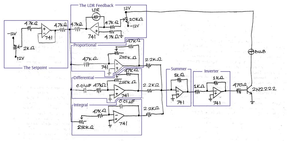
Circuit Analysis
Basically this P-I-D circuit is the controller part of the system. Several observations are made to determine the implication for the following cases: only proportional circuit is connected, both proportional and integrator circuits are connected, and lastly when proportional, integrator, and derivative circuits are connected together.
Proportional (P) circuit alone enables the lightning of the bulb when far from the LDR (light dependent resistor) but as it goes nearer to this LDR, it slowly dims. Proportional circuit controls the error and the output of the system with the right value of gain. Larger gain speeds up the reaction in reaching the system’s set point. However, offset is unavoidable in this type of circuit; thus, larger gain may lead to system’s instability because oftentimes it is hard to reach the set point due to the proportional circuit’s offset.
But with the presence of the integrator (I) circuit, it is possible to overcome the offset due to P and successfully reach the system’s set point. Even if P has a smaller gain, I can be a driving force of the system. As observed, P-I circuit enables the lightning of the bulb when it’s far from LDR but at a higher intensity (i.e. the bulb is brighter this time); it also slowly dims when it goes nearer to LDR but flickering occurs as the bulb becomes even closer to it. Flickering occurs when there is a higher gain in I because as it reaches the system’s set point, oscillation occurs.
To prevent this oscillation, derivative (D) circuit is connected to PI circuit. It speeds up the settling of the oscillation. However, when the derivative’s gain is high, overshoot tends to increase. This may go beyond the specification of the plant and damage it eventually. To prevent this, adjustments should be made in the gain of the other circuits (e.g. one may increase the gain of I to decrease the overshoot). With the presence of D, flickering is eliminated but the brightness’ intensity is still higher. When the room is dark, the bulb lights; it slowly dims when it goes nearer to LDR.
The three circuits are connected to the summer amplifier. This summer circuit adds the currents outputs from the P-I-D components. However, because of the linear relationship of the voltage and current in this circuit, it effectively adds the voltage outputs as well.
Tuning of P-I-D Controller
Potentiometers can be added on each of the components of the P-I-D controller. This would enable varying gain and time constants of the components and thus tune the circuit.
There are several methods in tuning a P-I-D loop. One of the methods, the the method that we used, basically follows this table:
Table 1. Effects of increasing parameters
Parameter
Rise Time
Overshoot
Settling Time
S.S. Error
P
Decrease
Increase
Small Change
Decrease
I
Decrease
Increase
Increase
Eliminate
D
Small Change
Decrease
Decrease
Small Change
We set the vary the values of P, I and D individually until the desired output is obtained. Each of the components, when changed, produces different effects on the Rise Time, Overshoot, Settling Time and Steady State Error. The ideal parameters of the circuit would be a fast rise time, a small overshoot, low settling time and a very small steady state error.
Another method for tuning the circuit is the "Zeigler-Nichols method". It starts in the same way as the previous method but varies the gains of the components for the next steps.
Table 2. Ziegler-Nichols method
Control
P
Tr
Td
P
0.5·Kc
-
-
PI
0.45·Kc
Pc/1.2
-
PID
0.6·Kc
Pc/2
Pc / 8
This method starts by looking for the Kc or the critical gain of the controller. This gain can be found by increasing the gain of the P component until the output becomes unstable. Instability would take the form of a sinusoid when feedback is eliminated. The next steps for the I and D components would basically follow the table.
In tuning the P-I-D controller, the first step is always to set the proportional gain first and zero out the other two components. The initial gain of P as set to 1 so that it would have a significant effect on minimizing the error. Setting it lower would have completely eliminated its effect on the error. In addition, the offset of the output from the set point would have been very large. To tune P, the gain on was slowly increased until noises become evident on the output. Normally, the gain would still be increased until the output becomes unstable. However, having a low noise rejection is just as undesirable. The resistance was then set to the value just before the noise appears. The integral part followed next. Its time constant can be varied by changing the resistance of the 47 KΩ resistor. Instead of placing a potentiometer in series to this resistor, it can completely replace this. By varying this resistance, the gain of I can also be varied. The potentiometer was adjusted until the light started to flicker. The flickering should be fast. If it is too slow, it means that I is already too high. The derivative part was then set next. The 47 KΩ feedback resistor can also be placed in series with a potentiometer or be replaced by it. The goal in tuning D is to first make sure that the response is fast. Its potentiometer was adjusted such that no noticeable overshoot occurred and the delay is not very obvious. Finally, the feedback resistance of the summer was set. By setting the feedback resistance to a value equal to the connecting resistors from the three components, the amplifying characteristic of the circuit shall be eliminated.
By comparing our output to the expected output from the table, we first set the P component high enough so the the SS Error was very small. At this point we did not observe any significant effect on the rise time. Overshoot was also not evident. By adding the I component, these parameters become more evident. The I component supposedly removes the SS Error completely. However, in our case, the P component was already high enough that there was only very little error that was left for the I component to correct. However, the I component also created a problem with the settling time. Having it too high would cause the output to blink with no end. This was further remedied by the D component. It removed the blinking or at least limited it to a few flickers. We noticed that it also seemed to settle faster. By following the methods above and observing the effects when varying some components in the circuit, we can build an ideal controller circuit for any plant or circuit.