I. The P-I-D
Concepts
The Controller compares a measured value from a process with a reference set point value. The difference or "error" signal is then used to calculate a new value for a manipulate-able input to the process that brings the process' measured value back to its desired set point. Unlike simpler control algorithms, the P-I-D controller can adjust process outputs based on the history and rate of change of the error signal, which gives more accurate and stable control. P-I-D controllers do not require advanced mathematics to design and can be easily adjusted or "tuned" to the desired application.
A control loop consists of three parts:
1. Measurement by a sensor connected to the process
2. Decision in a controller element
3. Action through an output device ("actuator")As the controller reads a sensor, it subtracts this measurement from the "set point" to determine the "error". It then uses the error to calculate a correction to the process's input variable (the "action") so that this correction will remove the error from the process's output measurement.
In a P-I-D loop, correction is calculated from the error in three ways: cancel out the current error directly (Proportional), the amount of time the error has continued uncorrected (Integral), and anticipate the future error from the rate of change of the error over time (Derivative).
"P-I-D" is named after its three correcting calculations, which all add to and adjust the controlled quantity. These additions are actually "subtractions" of error, because the proportions are usually negative:
1. Proportional - To handle the present, the error is multiplied by a (negative) constant P (for "proportional"), and added to (subtracting error from) the controlled quantity. P is only valid in the band over which a controller's output is proportional to the error of the system.
2. Integral - To handle the past, the error is integrated (added up) over a period of time, and then multiplied by a (negative) constant I (making an average), and added to (subtracting error from) the controlled quantity. I averages the measured error to find the process output's average error from the set point. A simple proportional system either oscillates, moving back and forth around the set point because there's nothing to remove the error when it overshoots, or oscillates and/or stabilizes at a too low or too high value. By adding a negative proportion of (i.e. subtracting part of) the average error from the process input, the average difference between the process output and the set point is always being reduced. Therefore, eventually, a well-tuned P-I-D loop's process output will settle down at the set point.
3. Derivative - To handle the future, the first derivative (the slope of the error) over time is calculated, and multiplied by another (negative) constant D, and also added to (subtracting error from) the controlled quantity. The derivative term controls the response to a change in the system. The larger the derivative term, the more rapidly the controller responds to changes in the process's output. Its D term is the reason a P-I-D loop is also called a "Predictive Controller." The D term is reduced when trying to dampen a controller's response to short term changes.
Applications
1. Used in process control where temperatures, pressures, etc. need to be optimally controlled.
2. PID is a relatively sophisticated compensation technique to improve the performance of a servo.
II. Feed-forward
Concepts
Feed-forward is a term describing a kind of system which reacts to changes in its environment, usually to maintain some desired state of the system. A system which exhibits feed-forward behavior responds to a measured disturbance in a pre-defined way - contrast with a feedback system.
Many prerequisites are needed to implement a feed-forward control scheme: the disturbance must be measurable, the effect of the disturbance to the output of the system must be known and the time it takes for the disturbance to affect the output must be longer than the time it takes the feed-forward controller to affect the output. If these conditions are met, feed-forward can be tuned to be extremely effective.
Feed-forward control can respond more quickly to known and measurable kinds of disturbances, but cannot do much with novel disturbances. [in contrast to Feed-back control, which deals with any deviation from desired system behavior, but requires the system’s measured variable (output) to react to the disturbance in order to notice the deviation.]
Feed-forward control can be likened to learned responses to known cues.
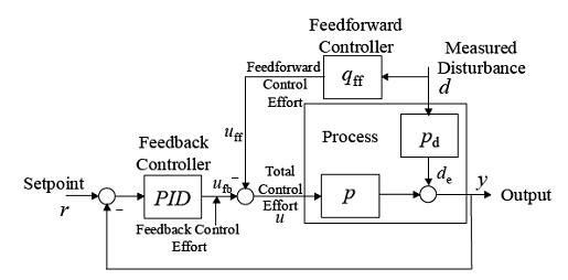
Figure 1: Traditional feedback/feed-forward control structure
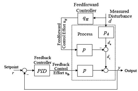
Figure 2: Equivalent block diagram
The redrawn equivalent block diagram clearly shows that the feed-forward part of the control system does not affect the stability of the feedback system and that each system can be designed independently.
Applications
A feed-forward system can be illustrated by comparing it with a familiar feedback system - that of cruise control in a car. When in use, the cruise control enables a car to maintain a steady road speed. When an uphill stretch of road is encountered, the car slows down below the set speed; this speed error causes the engine throttle to be opened further, bringing the car back to its original speed (a P-I or P-I-D controller would do this. Note that a good P-I-D control will return the car to the original speed, after an initial transient response).
A feed-forward system on the other hand would in some way ‘predict’ the slowing down of the car. For example it could measure the slope of the road and, upon encountering a hill, would open up the throttle by a certain amount, anticipating the extra load. The car does not have to slow down at all for the correction to come into play.
However, other factors than the slope of the hill and the throttle setting influence the speed of the car: air temperature, pressure, fuel composition, wind speed, etc. Just setting the throttle based on a function of the slope may not result in constant speed being maintained. Since there is no comparison between the output variable, speed, and the input variable, it is not possible to resolve this problem with purely feed-forward control.
Fortunately, the two types of control are not mutually exclusive; the feed-forward system just described could be combined with the feed-back system of conventional cruise control to allow quick response with the feedback system cleaning up for any error in the predetermined adjustment made by the feed-forward system.
Feed-forward does not have the stability problems that feed-back can have. Feed-forward needs to be a pre-calibrated cause → effect, feed-back does not. This is another way of saying what was said above – that feed-forward control applies to measurable disturbances with known effects.
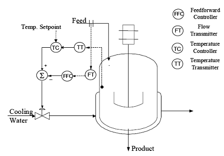
Figure 3: Feed-forward control on the feed to a continuously stirred tank reactor operating under reactor temperature control.
The continuously stirred tank reactor is under feedback temperature control. Feed-forward control is used to rapidly suppress feed flow rate disturbances.
III. Feed-forward + P-I-D
Combined feed-forward plus feedback control can significantly improve performance over simple feedback control whenever there is a major disturbance that can be measured before it affects the process output. In the most ideal situation, feed-forward control can entirely eliminate the effect of the measured disturbance on the process output. Even when there are modeling errors, feed-forward control can often reduce the effect of the measured disturbance on the output better than that achievable by feedback control alone. However, the decision as to whether or not to use feed-forward control depends on whether the degree of improvement in the response to the measured disturbance justifies the added costs of implementation and maintenance. The economic benefits of feed-forward control can come from lower operating costs and/or increased salability of the product due to its more consistent quality.
Feed-forward control is always used along with feedback control because a feedback control system is required to track set point changes and to suppress unmeasured disturbances that are always present in any real process.
IV. “Feedforward” Control mode
There is another type of Control mode called “Feedforward” that was proposed by Lee, Mendoza, and Pasicolan of Ateneo De Manila University. It is primarily a software implementation of their proposed algorithm that improves P-I-D control. This “Feedforward” Control mode has an adaptive algorithm. This “Feedforward” Control is different from the Feedforward control, which is commonly used in the industry. Unlike the Feedforward control used in the industry that responds to a measured disturbance in a pre-defined way, the proposed “Feedforward” Control mode algorithm “learns” from the P-I-D control mode and thus improves on the P-I-D’s shortcomings.
The “Feedforward” Control mode works under the principle that given a set point and a reading, a corresponding amount of energy can be injected into the system to achieve the desired set point. The “Feedfoward” Control mode is entered whenever an appropriate “Feedforward” parameter is found in the “Feedforward” lookup table given an initial error value. The error value is stored in a variable for the system to remember from what reading the system has started from and to remember which “Feedforward” value the system should improve when the feed forward mechanism comes short in achieving its purpose. The “Feedforward” time is stored in a counter that decrements to zero after which the system enters the P-I-D control and adaptive learning mode to compensate for any shortcomings of the “Feedforward” algorithm. The “Feedforward” mode also provides an anti-overshoot feature that preempts the “Feedforward” mechanism and switches the system to P-I-D control when the reading exceeds the set point when the “Feedforward” mode is commencing. Upon preemption, the “Feedforward” lookup table is updated accordingly to avoid the same mistake for this particular error value.
Although the “Feedforward” Algorithm enables the system to achieve the set point at a faster and more efficient rate, it does not guarantee that the set point would be achieved with pin point accuracy due to uncontrolled disturbances and instrumentation discrepancies between the software and hardware interface. With this knowledge at hand, the system can always correct the “Feedforward” parameters when the P-I-D control mode takes over after the “Feedforward” routine. The P-I-D algorithm compensates for the inaccuracies brought about by the “Feedforward” control mode and this compensation is used to update and improve the previous “Feedforward” information.


