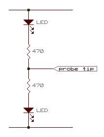
| use this probe to determine logic levels at ttl circuit nodes |
| know how to limit the current at the led | |
| assume the voltage across the forward-biased led to be 1.2 volts | |
| current is maximum when the probe tip is connected to either of the two power supply buses |
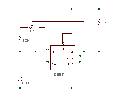
LM555 (timer) + resistors + capacitors + LED
 |
|
| o | a general purpose circuit to provide square wave of adjustable frequency |
| o | it can also be used to provide one positive-going edge or one negative-going edge at a time |
| o | capacitor charging and discharging times provide the integration functions that control the frequency of the oscillator |
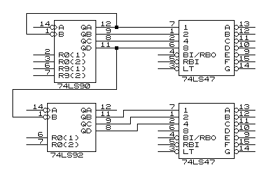
counters + decoders + displays
74ls90 - 0 to 9 counter
74ls92 - 0 to 5 counter
74ls47 - seven-segment decoder
 |
|
| o | cascading counters with their respective display circuits |
| o | note the operation of pins 2&3 and pins 6&7 in a 7490, and pins 2&3 in a 7492 |
| o | also note the operation of the 7447 |
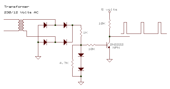
time base : zero-crossing detector
 |
|
| o | catching the instant of a "zero-crossing" to provide the time-base for the digital clock |
| o | note the resistor values and the diode configurations |
| o | the npn transistor is used as a switch to provide the timing edges |