Ma. Isabel Berdin
Sasan Simkani
Mary Angela Yu
PS 141 C Lab Report #2
Group 8 January 10, 2002
Part A – Operating the 7490 counter
a. What is the function of pins 2 and 3?
b. What happens when any of these pins (2 or 3) are raised to logic "1"?
c. What is the function of pins 6 and 7?
b. What happens when any of these pins (6 or 7) are raised to logic "1"?
e. What is the purpose of connecting pin 1 to pin 12?
f. What are the output pins?

The 7490 is a "decade counter", meaning it is able to count from 0 to 9 cyclically, and that is its natural mode. That is, the output pins QA (12), QB (9), QC (8) and QD (11) are 4 bits in a binary number and these pins cycle through 0 to 9, like this:
QD QC QB QA
0 0 0 0
0 0 0 1
0 0 1 0
0 0 1 1
0 1 0 0
0 1 0 1
0 1 1 0
0 1 1 1
1 0 0 0
1 0 0 1
For every pulse of the timer 555, the result would be the alternating lighting of the LEDs connected to it. Since 7490 is connected to 555 through pin 14 (input pin), for every pulse of 555, 7490 is likewise affected. Every time 555 pulses, 7490 changes count. One of its gates is pin 12. For our purposes, we can call it Output A. Notice that every time 7490 changes count, Output A (QA), which is 2°, changes from 0 to 1. Just like in decimals, when you add, sometimes you need to carry-over. It is the same with binary numbers. When you add, you sometimes need to carry-over. Therefore, the reason why pin 12 is connected to pin 1 is for the 7490 to be able to add properly, and would carry-over correctly. Pin 1 is connected to the other output gates, and would tell them what count the IC is currently in. The other output gates are pins 8, 9 and 11, and would separately change from 0 to 1, depending on the current count.
Pins 2 and 3 are connected to each other, as well as connected to the ground. Similar to the reason as to why pin 12 is connected to pin 1, we connected pins 2 and 3 to the ground so that 7490 would count properly. If either pins 2 or 3 is not connected to the ground, then that particular pin would be "high", while the other pins would be "low". This is the same reason why pins 6 and 7 are connected to each other and to the ground. However, the difference between pins 2 and 3 and pins 6 and 7 is that pins 2 and 3 resets to 0 rwhile pins 6 and 7 resets to 9. If pins 2 and 3 are raised to logic 1 (Vcc) and either pin 6 or 7 are raised to logic 0 (ground) then the chip will reset the output pins QA, QB, QC and QD to 0. On the other hand, if pins 6 and 7 are 1, then the chip will reset to 9.
Part B – Operating the 7442 BCD to Decimal Decoder
- What are the input pins of the 7442?
- How did you connect them to the 7490?
- Describe the behavior of the LEDs connected to the outputs of the 7442?

Pins 15, 14, 13 and 12 (which are called Inputs A, B, C and D respectively) of 7442 are connected to the Outputs A (pin 12), B (pin 9), C (pin 8) and D (pin 1 I) of 7490 respectively. Since 7490 is a counter, and 7442 is connected to the outputs of 7490, then, in layman’s terms, 7490 tells 7442 what count it is currently in. A resistor is connected to pin 5 of 7490, which in turn is connected to the VCC. This resistor is also connected to 10 LEDs and these LEDs are each connected to pins 0-11 (with the exception of pin 8. which is connected to the ground). Due to the fact the 7490 tells 7442 what number it is currently in, the LED connected to the pin with that number would light. In other words, the 7442 decoder interprets the BCD combination from the output A, B, C and D of 7490 and then allows the LED connected to that interpreted decimal output pin light up. For example, if the outputs (from 7490) entering the 7442 are 0(A), 0 (B), 1 (C) and 1 (D), then the LED connected to the Decimal 3 output pin (pin 4) will light, since 3 is the converted decimal number of 0011 (BCD).
Part C – Operating the 7447 seven-segment decoder
a. What are the input pins of the 7447?
b. How did you connect them to the 7490?
c. Describe the behavior of the LEDs connected to the outputs of the 7447?
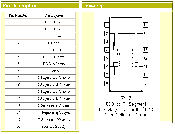
 
The 7447 BCD to Decimal Decoder produces outputs that are active low. Active low means that when a segment is activated the Decoder outputs a ground. All the other segments are high and the Decoder outputs a supply voltage. Because the 7447 produces outputs that are active low it must work with a 7-segment display that is already connected to a supply voltage.
The input pins 7 (A), 1 (B), 2 (C) and 6 (D) of 7447 are connected to the output pins 12 (A), 9 (B), 8 (C) and 11 (D) of 7490 respectively (output A of 7490 is connected to input A of 7447, output B connected to input B, and so on). Therefore, just as 7490 tells 7442 what count it is currently in, the same information is also being passed to 7447. However, in the case of the 7447, a 7-segment LED is used to display the decimal value of the BCD inputs from 7490. For example, when the BCD input entering the 7447 is 0 (A), 1 (B), 0 (C) and 1 (D), then the decimal number 5 will appear on the 7-segment LED, since 5 is the decimal conversion of 0101 (BCD).
Part D - General Observations.
If you were to describe the experiment to your 12-year old younger brother or sister, or to your mother, how would your description read?
A counter called 7490 counts from 0 to 9 cyclically. After it reaches 9, it resets back to zero to start counting again. The numbers 0 to 9 has a corresponding 4-digit code, which is a combination of 0’s and 1’s, and at the same time becomes the output of the counter 7490. The 4 digits of the code is then inputted in a device called a 7442 decoder, which could interpret the code and convert it to a decimal number. Connected to the 7442 are objects similar to a light bulb, the LEDs. Those LEDs are numbered from 0 to 9, and so after the 7442 converts the 4-digit code into a decimal number, the LED with that converted number will light up. Since the counting is from 0 to 9, the LEDs will light up one by one according to their respective numbers. The 4 digits of the code also enter another device called a 7447 decoder, which is connected to a machine that could display numbers. The 7447 would also convert the inputted code into a decimal number, and would then tell the other machine to display the interpreted number. For example, if the code for number 7 is inputted in the 7447, then the number "7" would be displayed by the other machine. Also, since the counting is from 0 to 9, the numbers "0" to "9" will be displayed one at a time.
|