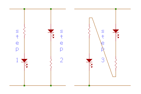
A. What purpose do the resistors have in the Step 1 & Step 2 diagrams?
In both the first (Step 1) and second (Step 2) set-up, the presence of the resistors is very important in order to make the light emitting diodes (LED) light up. Since the LED's operate at a relative low voltage of 1-1.2 volts, and draw a current of around 10 mA, a resistor has to be placed in the circuit, in series with the LED, so that it could limit the current passing through the LED, and thus preventing it from burning. Moreover, in order to allocate a voltage drop of 1.2 volts across the LED, a resistor with a minimum value of 380 W has to be inserted in the circuit. A value less than 380 W would not be able to make the LED light up.
Computation:
R = V / i
R = V / I
R = (5V - 1.2V) / 0.01 A
= 380 ohms

B. How do you recognize 1's and 0's using the circuit you built in Step 3? Give a brief explanation.
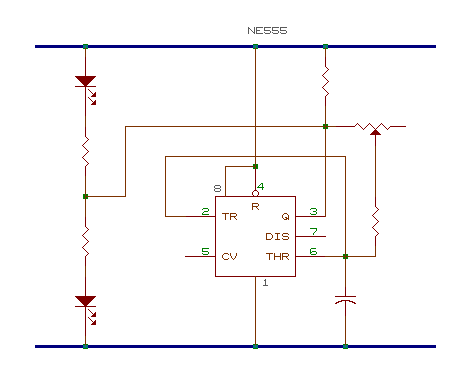
Using the circuit built in Step 3, in order to recognize 1's (highs - between 2.4 and 5.0 volts) and 0's (lows- between 0 and 0.8 volts), we must first connect a logic probe in between the two resistors. In that way, you could connect the probe to either the ground (logic 0) or to the 5 volts (logic 1). When the probe is connected at logic 0, current will pass through the top LED and "empty out" in the probe, thus making only the top LED light up. On the other hand, when the probe is at logic 1, the probe would be supplying the current to the bottom led, which would then "empty out" to the ground, making the bottom LED light up.
C. What is the purpose of the capacitor and resistor to control the speed of the change from "1" and "0" in the diagram. Give a brief explanation.

Both the capacitor and resistor act as a timer for the speed of change from "1" and "0" because the rate at which the capacitor charges or discharges depends on the value of the resistor. When the charging current passing through the resistor is high (low resistance), the capacitor would be charging faster. Conversely, if the charging current in the resistor were low (high resistance), the charging of the capacitor would also be low. In other words, the resistance to the flow of the current controls the speed of the charging or discharging of the capacitor.
D. How does the 555 run an "oscillator"? Give a brief explanation.

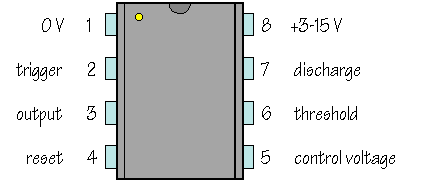
In making the two Light-Emitting Diodes (LED) light, we must consider the ne555 chip. This chip has 8 pins. Each pin is designed for a particular function, but for this particular experiment, what are important are pins 3, 2, and 6. Notice that pins 2 and 6 are connected, and that both of them are connected to pin 3. We put the chip, as well as the resistors, capacitors and the wires in an electric board. There are Vcc lines that can be found inside the board. The Vcc lines are the lines where the voltage coming from the source travels. Whenever the voltage (Vcc) passing through the pins 2 and 6 is 2/3 and above of the total Vcc, it tells pin 3 to go "low". Because pin 3 is connected to the probe, pin 3 therefore serves as the ground for voltage coming from the source, passing to the top LED and to the resistor. Given this situation, only the top LED would light, since there would be no voltage going to the bottom LED. On the other hand, when the Vcc is below 1/3, since it would obviously go down, the pins 2 and 6 would tell pin 3 to go "high". Whenever this happens, only the bottom LED would light. Why? You see, the voltage's path would be from the source to pin 3, to the resistor, to the bottom LED and, finally to ground, where the voltage "empties out". The top LED would not light for no voltage would be running through it. Imagine now how it would be if the situation above would be a continuous pattern. There would be a so-called "blinking of the lights". Since pins 2 and 6 are connected to the capacitor, you can control the speed of which the voltage comes and goes.
|