| back to top (s larios / r caranto / i soriano / c pacifico) |
 |
|
Light Sensitive Sliding Door
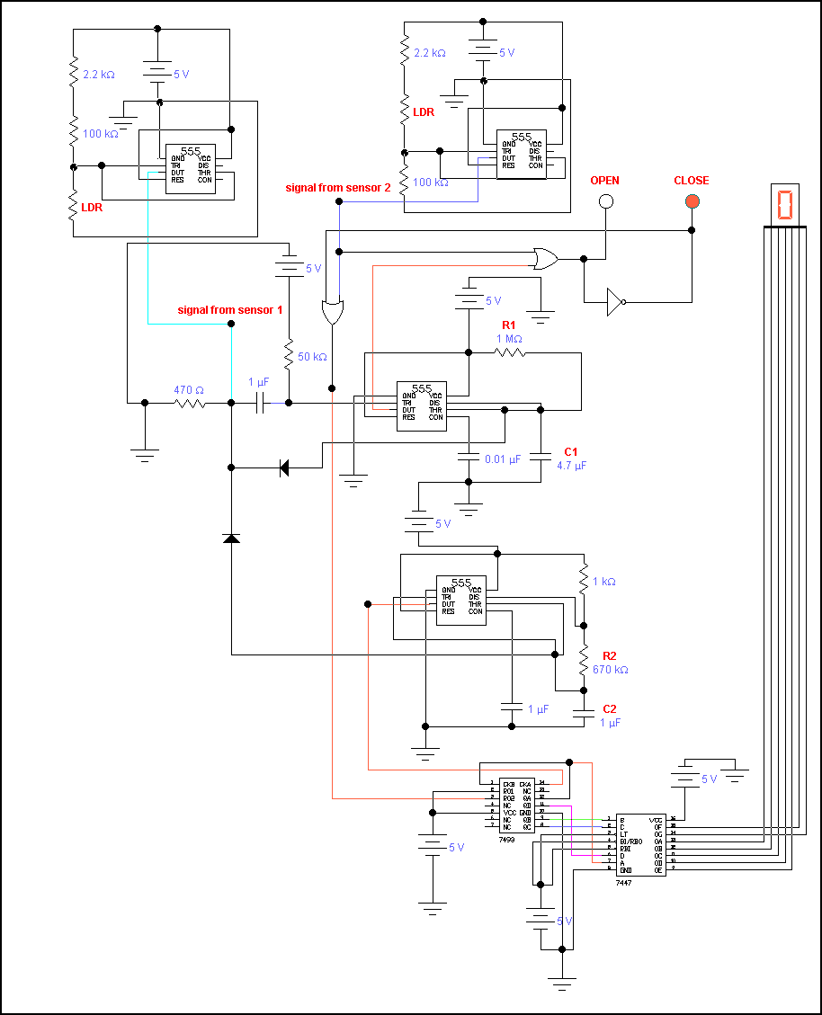
Concept: The theory behind this "Light Sensitive Sliding Door" project is that a motor-operated door will automatically open whenever a man passes through either one of the two sensors. The first sensor is placed a few inches away from the second sensor. Whenever something blocks the path of the light that triggers light dependent resistor, the whole circuit will operate and the door will open. However, to give some ample time to let the man pass through the door, a delay of 5 seconds was inputted in the circuit to ensure safety. A second sensor was also included in the system to tackle the problem of a slow walking man. In case the man takes longer than 5 seconds to get thru the door, a second sensor, placed at a near distance to the door, was added. This time, though, there is no more delay time. Once the second sensor is triggered, the door opens, and once the man passes thru, it automatically closes. In case the man "surprisingly" decides to stay in between the two sensors, the same scenario will occur as if he passed thru. The door will remain open for 5 seconds, since to get in the middle, he has to trigger the first of the two sensors, and then automatically close. In case he decides to go thru after all, he will trigger the second sensor and then the door opens and closes once he passes thru. But in case he decides to go back, he triggers the first sensor again, prompting the door to open again for 5 seconds. This operation is one sided, though. It can only tackle one way of either entering or exiting. To solve the case of having to open and close the door for a common entrance and exit, we just have to "mirror" the circuit to the other side, copy the exact concept and materials, and the problem for a common way is solved. Or we can just another passage to get in or out in another side of the building. Suppose a man decides to stay in the sensor, the door will just remain open, since at that instance, the circuit gets a signal of a passing man continuously, so it will remain open until the man goes out of the sensor, and then after the 5 second time, the door closes again, unless the man was between the second sensor, though. Problems raised such as no ample lighting was solved just by adding a light source, like a bulb, to concentrate the input of light towards the light dependent resistor. Another was what if the man decides to hop or skip over the sensor. Then that means the door will not open since he has not triggered the system. But to get thru, he still has the second sensor, so he can still enter without having to go back to the first sensor. Circuit Operation The heart of the light sensors of this circuit is the light dependent resistor (LDR). The sensor circuit uses the LDR to provide the appropriate voltage drop depending on the amount of light that can be seen by the LDR. Basically, the LDR has a resistance of approximately 1M( under dark lighting and approximately 2k( under bright lighting. A 555 timer is used to provide the output voltage. The signal to pins 2 and 6 of the 555 timer come from either the LDR or the 100k( resistor depending on the light condition and its desired output. The signal coming from the sensor is then fed into the main circuit. The main circuit is also uses a 555 timer. The timer is wired in the astable mode. Pin 6 is connected to pin 2 using a diode. LED's were also used to give the state of the door. Green meaning open and red meaning close. Initially, pin 2 is high and pin 6 is low and the output pin 3 is low thus the red LED lights up. The moment someone blocks the light source of sensor 1, the signal in pin 2 goes low momentarily enough to trigger pin 3 to go high lighting up the green LED while pin 6 rises a little bit but still remains low due to small voltage entering the diode. As soon as the person leaves sensor 1 and permits the light to reach the LDR, pin 2 shoots up momentarily and then remains high. The diode connecting pin 2 and pin 6 becomes reversed bias and goes out of conduction and capacitor C1 charges through R1 until it reaches 2/3 Vcc then pin 6 turns the transistor inside the timer on, output pin 3 goes low, then C1 discharges through R1 and the red LED lights up signaling a closing door. At this stage, the main circuit goes back to its initial state. The time of charging is the time allotted the person to cross the door and can be controlled by the changing the values of C1 and R1. Sensor 2 on the other hand acts as a safety measure. It should be positioned in such a way that when the person arrives at the doorway and the allotted time to cross expires, the doors won't close. Finally, the outputs of the main circuit and sensor 2 go through an OR gate and into the LEDs. Also to provide the person with some visual aid, a seven-segment display is used to show the time before the door closes. A clock pulse generator using a 555 timer was wired to serve as the clock signal of the 4-bit binary counter (7493). A diode was again used in a similar fashion as to the main circuit to tell the clock pulse generator only start counting as soon as the person leaves sensor 1. The reset pins (2 & 3) were wired in such a way that the display becomes zero whenever a person stands in the way of sensor 2 or when the red LED is lit. The outputs then of the counter are fed into the BCD-to-seven segment decoder/driver (7447) and then are connected to the seven-segment display. |
| back to top (j largo / d yason) |
|
|
LAB REPORT
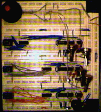
This project is a combination of logic circuits and timing devices wired together to produce a sort of a randomized numbers game. This was designed to exhibit the properties of digital devices capable of producing a numbers game wherein the output (seen in a seven-segment display) must be kept unpredictable. Moreover, it is composed of, namely, a switch, 2 555 timer drawn side by side, a 7490 BCD decade counter, a 7447 BCD-to-seven segment decoder/driver and a seven segment light emitting diode (LED) display. We built a set of three of this circuit to come up with three outputs from the LED display. 555 TIMER/RANDOMIZER As shown in our schematic diagram, the 555 timer is connected as an astable multivibrator. Both pin 2 (trigger) and pin 6 (threshold) inputs are connected to the two comparators and to the external capacitor. The capacitor charges toward the supply voltage through the resistor and the potentiometer. Pin 7 (discharge) wired to the internal transistor T1 is connected to the junction of those two resistors. When we supplied the circuit with +5 volts, the capacitor’s initial state will be uncharged. Thus, both pins 2 and 6 will be near zero volts. The lower comparator senses this state and sets the flip-flop causing the output to HIGH (logic 1). This will cause the capacitor to start charging through the resistors. When the charge of the capacitor reaches 2/3 Vcc, the upper comparator resets the flip-flop causing the output to go LOW. This causes the external capacitor to discharge. The cycle continues to repeat with the capacitor alternately charging and discharging. The primary 555 (timer) and the secondary 555 (randomizer) are both connected in this kind of configuration. The output (pin 3) of the randomizer is wired to the junction of the resistor and potentiometer of the primary 555 timer. This alters the period and time interval in which the capacitor charges or discharges. When pin 3 of the randomizer is either HIGH or LOW, the current through it causes a change in the charging time of the capacitor. Thus, irregular time intervals cause a random output in pin 3 of the timer. 7490 BCD DECADE COUNTER The 7490 BCD decade counter counts the number of pulses arriving at its input. The number of pulses counted appears in binary form on four pins (A,B,C,D) of the 7490. The output from the 555 timer is connected to the pin 14 of the decade counter. The decade counter operates under normal conditions and outputs the number in binary form through pins 8,9,11 and 12. These four pins constitute the number of significant digits the decimal number is to be converted to its binary equivalent. 7447 BCD-to-7 SEGMENT DECODER/7 SEGMENT LED DISPLAY In a BCD signal from timer, four bits are encoded by the decade counter to represent each decimal digit. These four bit BCD group are decoded into the normal decimal digits by the use of the 7447 decoder/driver ic chip. The decoded signal goes to the seven segment LED display wherein the decimal number can be seen. In addition, the 7447 provides enough current to drive the seven segment LED display. The seven segment LED display is an array of eight light emitting diodes which are optically magnified to form seven individual elements and a decimal point. MAIN SWITCH The main switch is composed of a diode, a resistor, a potentiometer and an external capacitor in parallel with the switch. Basically, the switch works due to the “grounding” of the trigger and threshold pins of the 555 timer. The timer is in normal condition when the switch is open. When we shorted the switch, pins 2 and 6 will automatically be connected directly to the ground through the diode and resistors. We must note that when the trigger and threshold inputs are zero (or near zero) volts, the lower comparator sets the flip-flop causing the output to go HIGH. This cause the timer’s output to remain constant, thus, paralyzing the decade counter’s normal operations. The LED display will stop and the number displayed is part of your hopefully “lucky” combination. |
| back to top (e uy / n hernandez) |

|
|
|
|
Coffee Maker
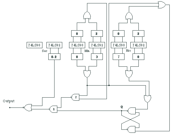
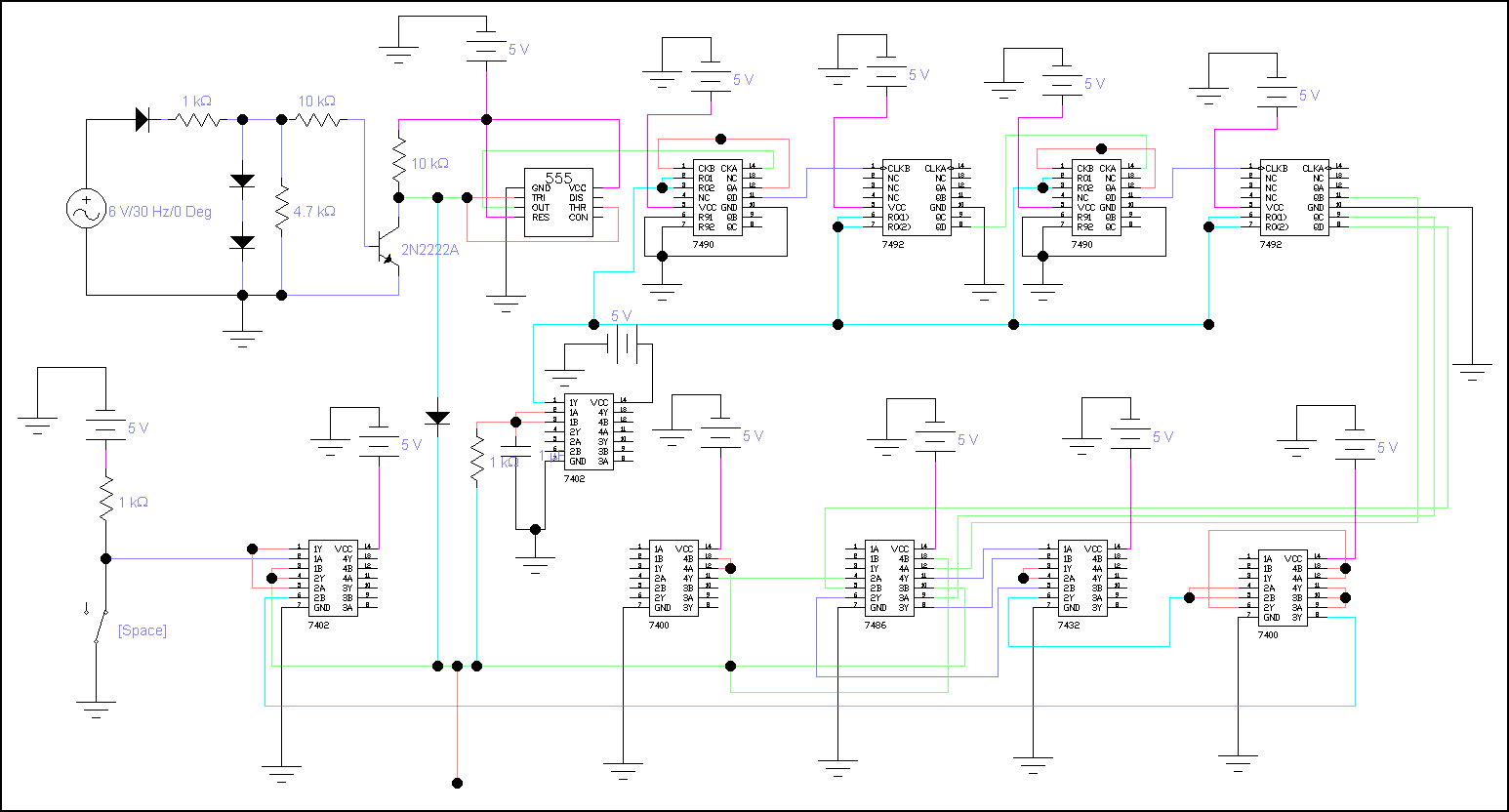
Introduction Most people, especially students, drink coffee as part of their lifestyle or as a necessity in order to survive. For instance, students need coffee to cope up with those sleepless nights needed in doing projects or studying for exams. This gave us the idea for designing our project. The main blocks of our design of the coffee maker are timer, switch (input port), comparator and resets. The last part is the output, which is to be connected to a motor, which we were not able to do. Timer This part of the circuit is made up of active devices, 555 timer, 7490 and 7492 counters. The active devices receive a sinusoidal input from the supply. It would then send an oscillating sinusoidal signal to the 555 timer. The output of the 555 timer is also oscillating, however, it is now a square wave, which signifies clock pulses of alternating 1's and 0's. This signal is then send to the series of 7490 and 7492 counters, which in our case count up to seconds. The signal from the 555 is sense by the 7490, a 4-bit decade counter, which counts from zero to nine. It senses the negative going pulse of the output signal of the 555 timer. That is it only counts when the signal is a positive going pulse. The most significant bit of the 7490 (pin 11) then serves as the input pulse for the 7492. A negative going pulse also triggers it, that is, it would only start counting upon the transition of the 7490 from 9 to 0. Up to this part, the timer counts up to milliseconds. Again, the most significant bit of the 7492 (pin 8) serves as the input pulse for the second 7490. It would then be connected to the 7492. And up to this point the timer now counts up to second, which is the desired time for a cup of coffee to be filled up. The signal from the three output pins of the 7492 would then be transmitted to the comparator, which we will discuss in the third part. Switch (input port) As we on the switch, the normally closed part would now be open and one pin of our sequential logic circuit (SLC) will be high. This would then output one, which is our desired signal for our motor to work. This signal is then coded based on the expected time to fill a cup of coffee. In our case, we only take a specific code, which is 101. This code is then transmitted to the comparator. Comparator In this part, we use the 7486 comparator, which is composed of XOR gates. The output of one gate would be one if the two input signals were not the same. As soon as the two signals are the same, the output would be zero. The output of the timer and the input port are the two input signals, which is to be compared in this part. As we switch on the coffee maker, the two signals are different. Some gates of the comparator would output 1. In time, the signal from the timer would be the same as the encoded signal. This would then result for all the gates of the comparator to be 0. To capture all the three outputs of the comparator we input it to a 7432, which is composed of OR gates. The output of this chip would be one if any one of the gates of the 7486 is 1. It would only output 0 if all the gates of the 7486 has a 0 output. Resets As we design the circuit, some problem arises. One of the major problems is that some parts of the circuit need to be reset as soon as the output of the 7432 shifts from 1 to 0. Two of the parts need to be reset. The counters should be reset so that it would again start counting from 0. We also need to reset our SLC. To reset the SLC we just inverse the output of the 7432, which is connected to one of the inputs of the SLC. Whenever the motor is working, the output of 7432 is 1; the signal of one of the inputs (set) of the SLC is low which would maintain the output of the SLC to be 1. As the motor stops, the output of the 7432 is 0, which would turn one of the inputs of the SLC to high. This pulse would then result to an output of 0 for the SLC. For the reset of the counters, we use an initializer. In this reset we input in a NOR gate the signal from a low pulse (through the capacitor) and a pulse dependent on the output of the SLC (through a resistor). The output is then send to the reset pins of the 7490 (pins 2 and 3) and 7492 (pins 6 and 7). In addition, we also encounter a problem regarding the start of the counting of the timer. Although we have the power supply ON, we do not want the timer to start counting until we have switched the device. In order to resolve this problem, we attached a diode in between the timer and the output of our SLC. When have not switched the device, the current would flow to this diode instead of the 555 timer. As we switch on, the SLC would output 1 making the diode to be reverse biased so that it would be open, and the current would now flow to the 555 timer to start counting. Output (motor) We want that this part would output 1 as we switch on the device. This would then be 0 if the timer would be equal to the encoded signal. At first, we obtain the signal to the output of the comparator. However, we noticed that it would just be 0 for an instance that the values are the same and then, it would be 1 again. Even if the counters have been reset, (all outputs are 0) we have a 0 output from the SLC producing another coded (010) signal, which is the inverse of our original coded signal (101). In order to solve this problem, we have tap our output to the SLC output since, it would be 1 as we switched on the device and after the reset it would be 0 until it is switched on again. Recommendations This coffee maker is not yet calibrated, that is, we have not really taken the time for the cup of coffee to be filled up. We just take a code (101) and take it as an example of a time to fill up a cup of coffee. The initializer that we use as a reset for our counters is not very reliable. The resistor may not really pull down the pulse to 0. A Schmitt trigger may well be use to implement the reset for the counters. In addition, the motor has not been implemented. |
| back to top (f mallen / j venturanza) |
|
|
Rhett Francis Mallen
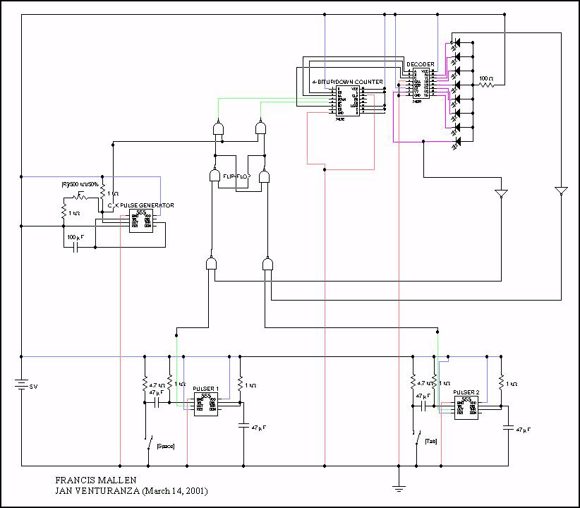
Januel Venturanza 3-ECE ELC 111 (laboratory) final project LED Pingpong Ballgame Our project is an electronic simulation of a Ping-pong game. Constructing a series of LEDs lighting up according to a particular sequence simulates the movement of the Ping-pong ball. This circuit allows two players, each controlling a push-button switch, to play the Ping-pong using eight indicator lamps (LED) in a row. The ball is moved by a clock source that triggers an up/down counter to shift the ball either to the right or to the left. Like in a real Ping-pong ball game, the player must hit the ball once it reaches his side. That is to say when the ball is moving to the right, the right-hand player must press his push button at the time the ball is in its rightmost position. If the player pushes at the correct time, the direction of the shift reverses and this time, the ball moves to the opposite direction — to the left. Correspondingly, the left-hand player must then return the volley by pressing his push button when the ball is in its leftmost position. Thus, as in the real game, the two players will take turns pushing their buttons at the right time, thereby making the "ball" travel back and forth. The project requires 4 digital circuits, each one having a particular task as required by the electronic game as a whole. These 4 circuits are the following: decoder, up/down counter, clock pulse generator and the pulser. Specifically, the group requires a 3x8 decoder to specify the "movement" of the ball. The decoder's eight outputs correspond to the eight LEDs utilized in this project. In this circuit, we used a 74LS138 IC chip. Its truth table is shown below. 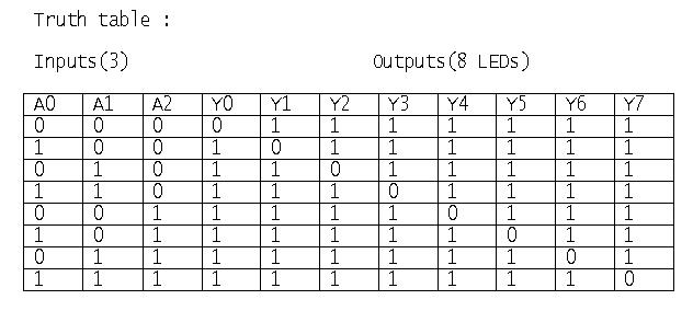
Since the chip is designed to give an output of 0 only at one of the eight output terminals at a given instant, we have placed the LEDs in the circuit such that its negative terminal is connected to the output pins of the decoder so that only one and not seven of the eight LEDs will light at a particular moment. To supply the eight combinations of inputs for the decoder, we used a presettable 4-bit binary up/down counter (74LS193) that has count up and count down clock modes that operate synchronously. Actually, it counts from 0 to 15 that is why it has a 4-bit output but we only used the three output pins of the counter since obviously, we only need three as inputs to the decoder. The task of this part is to regulate the "movement" of the ball. A ball "moving" in a particular direction takes either the count-up or the count-down. Thus, the ball travelling back and forth means that the counting shifts continually from count-up to count-down and then back again, as the two players keep hitting their buttons right. The counter counts up whenever its pin 5 senses a low to high transition while pin 4 is high and on the other hand, it counts down whenever its pin 4 senses a low to high transition while pin 5 is high. The low to high transition comes from the pulse (square wave) generated by the oscillator or clock pulse generator, which drives the clock modes of the counter. The ball should only reverse its direction only if the paddle switch of the player is pressed at the right time. Otherwise, the direction of the ball will not change. To do this, we need a very short pulse that rides together with the clock pulse at the correct instant. Due to time constraint, there are certain improvements, however, that we want to raise in this project. First of these is regarding the restart option of the game. Ideally, if a player pushes his push button too soon or too late, the ball should disappear at the end and the player who has just scored should be able to restart the game by pressing his push button. But in our project, the ball continues to move in one direction and reverses direction only when the time comes that the other player presses his button correctly. The circuit that we designed does not yet make the ball disappear if a player pushes his button at the wrong time. Also, a number of options can be provided to make the game more interesting like the different rates at which the ball can move and a display that will keep the scores of the players. |
| back to top (e escolastico / r que) |
|
| back to top (e victorino / c marasigan / j reyes) |

|
|
Circuit Explanation of Time-delay lock
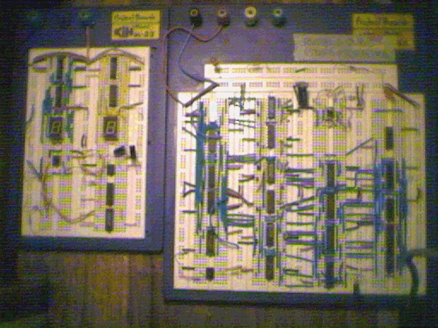
Circuit 1: Our prototype circuit acts only as a timer for our desired circuit. The 555 Integrated Circuit Timer sends a pulse that is passed on to the 7493 IC Counter. The 7447 decoder would then show the output through a 7-segment display. As was said, the 1st circuit is only a timer since we weren't able to reach the starting and stopping of the circuit's countdown. Circuit 2: The 2nd circuit is the circuit that we wanted to build but unfortunately weren't able to due to some circumstances. The 2nd circuit features four seven-segment displays to act as the display of the counter, four 7447 decoders for the display, four 74192 Presettable Synchronous Up/Down BCD Counters, a 555 timer and numerous other IC's. The 2nd circuit, unlike the 1st one, has a flip-flop that acts a control circuit for the starting and stopping of the Time-delay. Here is the explanation for the circuit: The counters are divided into two parts, the first one would be the second counter and the other would be the minute counter. With this circuit, we would be able to countdown from 59 minutes, 59 seconds to 0'0". With this desire comes a complication – the ten's counters should only be able to reach the number 5, this is solved by presetting the 74192 counter for the ten's to 5. When counting, a countdown circuit counts from the higher to lower set of numbers (in this circuit's case, from 59'9" to 0'0"). To accomplish this, the 74192 counters count the high to low transition of the signal from the 555 timer. The 74192 at the 1's second counter would countdown from 9 to 0 and would then borrow from the 10's second counter. The cycle would continue as the 1's second counter countdown's to zero and borrows from the 10's second counter until it reaches zero, and would then borrow from the 1's minute counter (and then to the 10's minute counter when it hits zero). The circuit should stop when it reaches 0 minutes and 0 seconds. The next part that would be explained would be the flip-flop that is used for the starting and the stopping of the circuit. When the switch is turned on and if the timer is not equal to 0'0", the output would be high (its working condition). But if the timer is 0'0", the output of the flip-flop would then be low and the countdown would stop having reached its limit. When the start switch is turned off and then turned on though, the countdown would be reset and it would start again. *2nd circuit downloaded from the Hobby of Electronic Circuit Engineering Website |