Interfacing
the Transmitter to the
Parallel Port
Rio Ong
Don Carlo Dy
back to CE150
Since we have already interfaced the software to the hardware by being able to control the output of the parallel port and isolating the computer from the outside using optoisolators, we are now in the position to interface the transmitter. This will be the last stage of the project design implementation. As was discussed, the first four data lines of the computer (pins 2 - 5) was used to interface the hardware to the software. Each of the four pins correspond to each of the commands. These commands are: "Go", "Back", "Left" and "Right". Pin 2 corresponds to the "go" command, pin 3 to "back" command, pin 4 to the "left" command and pin 5 to the "right" command.
The transmitter and receiver to be used were included upon purchasing the Radio-Controlled Car. What was done, was to remove the transmitter circuit from the remote and re-simulate everything in the hand-held remote. These includes, 9 volts supply which we did by tapping 9 volts from a dry-cell. Another is the connection of the switches and wires. We simplified the transmitter circuit by removing the 2 joy sticks in the hand-held remote and replace it by supplying 9 volts to a specific input. The diagram of the simplified transmitter circuit appears below. Looking on the right side of the picture on the box indicated by "transmitter", one can notice the 5 wires of the transmitter. The black line is the 9-volt supply. The yellow wire corresponds to the "go" input line, blue to the "back" input line, white to the "left" input line, and green to the "right" input line. By connecting each of these input lines to the 9-volt supply (black wire), the specific command is transmitted, received by the remote car, and t
he command is executed. For example, if the yellow wire is fed with 9 volts, the car will go forward. In the case of transmitting two commands (e.g., forward and right), 9 volts is fed into the yellow and green wire. So the problem now is how to connect the 9-volt supply wire to each of the input lines by using only TTL output from the optoisolators connected to the parallel port of the PC.
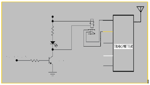
This could easily be implemented by using relay-switches, and transistors. For this discussion, only one of the commands is discussed since the others share the same hardware implementation and discussion as this.
Referring to the diagram below, the input of the circuit is coming from the TTL output (pin 2 of parallel port) of the optoisolators. And the transistor (Q2N3904) serves as a switch. If the transistor is saturated by applying TTL high logic into the its base, the emitter of the transistor is then immediately switched to ground. This results to a complete circuit of the relay switch causing a flow of current across its coil. This then induces a magnetic field to the mechanical switch of the relay and closing the normally open pins (opening the normally closed) of the relay. This then connects the black and yellow wire of the transmitter and thus sending a "go" signal to the car.
If for example, a low logic is outputted by the optoisolator, the transistor is not saturated. The transistor's emitter retains its no connection to the ground. This implies that the circuit of the relay switch is not complete and current would not flow through the coil. There will be no magnetic induction to trigger the mechanical switch from switching. The normally open pins of the switch is retained and 9-volts is not supplied to the "go" input line (yellow). Hence no signal is transmitted.
The LED and 1K resistor are placed for purposes of displaying the status of the input signal. If a high logic is inputted, this LED will light up. Otherwise, this remains off.
As for the other commands, the same components are needed: relay switch, transistor, resistors and LED. The same connections are made for the other commands. The diagram of the hardware is shown below.
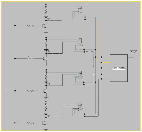
As can be seen, each of the input lines of the transmitter (yellow, blue, white, and green wires) are connected to the black 9-volt supply if the corresponding relay switch and transistor are triggered. In short, as was discussed above, each of the input lines are connected to the black wire when a high logic is inputted to the base of the transistor causing a transmission of a particular command.
|