|
1
|
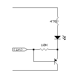
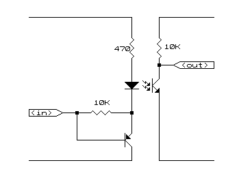
this circuit is provide high voltage isolation between two "ttl" circuits.
|
| 2
|
principle of operation :
- at design conditions, a logic "1" provides 2.4 volts at the input.
- the net voltage at the resistor is (5 - 2.4 - 0.6 - 1.2), or 0.8 volts.
- this produces a current of (0.8 * 1000 / 470), or 1.7 ma.
- if this current is producing an unwanted logic "0" on the other side, the 470 ohms may be increased, or the collector resistance at the other side could be reduced, or a resistor inserted in series with the base together with a corresponding resistor connected to the emiter and the +5-volt supply.
- on the worst case, that the resulting current is still unacceptable, two diodes could be connected in series with the circuit to have no voltage across the resistor. should it be required, the value of the resistor could be decreased to provide a larger current to the led section of the circuit.
- the pnp transistor is provided as a buffer to the input, especially, if this comes from the computer port.
- at design conditions, a logic "0" provides 0.8 volt at the input.
- the net voltage at the resistor is (5 - 0.8 - 0.6 - 1.2), or 2.4 volts.
- the current across the resistor is (2.4 * 1000 / 470), or 5.1 ma.
go to top next
|

|
|
| 3
|
principle of operation :
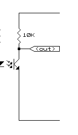
- the important requirement is for this circuit to drive the load down to 0.8 volt.
- the collector resistor is provided simply to neutralize the effect of a collector-emiter current leakage, and to provide a pull-up for the input.
- the resistor value may be decreased, depending upon the resulting conditions.
- on the worst case, a buffer may even be added to increase the capacity of the current driver to the load.
go to top prev
|

|
|
| 4
|
it is most important to take note of the reverse-biased diode at the collector, and across relay. inductive circuits, like relays, produce magnetic lines of force when energized. when the energizing current is removed, the magnetic lines of force will collapse and induce voltage at the relay coil which is opposite to the direction of the driving voltage. at this point, the diode will conduct and prevent the high inductive kick (voltage) from damaging the solid state devices along its electrical path.
|

