|
1
|
go to top
next
previous
Rule of Thumb
One of the efficient ways of converting from one voltage level to another is to convert the voltage or current signal into current of a usable magnitude at the remote location.
At the receiving end pass this current through an appropriate resistor, where it will provide the appropriate voltage drop that can be fed into a sensing circuit.
This method usually goes by the name of "current-loop". In field instrumentation applications in industry, this is more popularly found in "5-to-20 ma" current loops.
|

|
|
|
2
|
go to top
next
previous
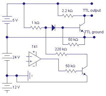
A +12V/-12V OpAmp which senses analog input conditions. The output must drive a TTL gate whose ZERO is at
a) +24Volts, b) +7Volts, c) 0Volt, and c) -12Volts
An analog signal would be generated by the 741 comparator. Any voltage lower than 0.4 Volt would not provide a forward bias to the transistor connected at the end of the 50K resistor. The NPN transistor at the TTL voltage level is initially forward biased, providing a TTL output level of logic "0".
An increase in the 741 voltage beyond 0.4 volt will cause the NPN transistor to start conduction. The upper level transistor would start to go out of conduction when the voltage at the anode of the diode reaches the vicinity of 1 volt (the exact value is dependent upon the operating temperature and the characteristics of the diode and the transistor).
Note. The diode is provided at the upper level transistor in order to limit any reverse-bias at the base-emitter junction of this transistor. It is also a good practice to provide a reverse-biased diode at the base-emitter junction of the lower transistor for the same reason, but with a slightly different configuration.
|

|
|
|
3
|
go to top
next
previous
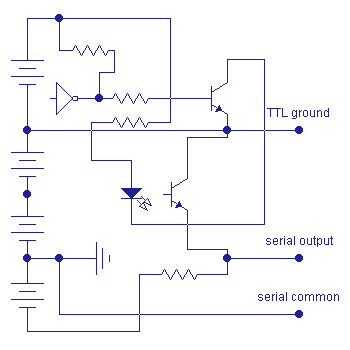
The TTL circuit on the upper portion of the circuit will send current to the LED portion of an opto-isolator (such as a 4N25). Light is emitted and sensed by the light-sensitive base-emitter junction of the NPN transistor, causing it to conduct and bring the emitter to a high level. This is the common-collector configuration. The emitter could be "OR'ed" with other circuits of the same configuration.
The circuit could also be configured as a common-emitter circuit by simply exchanging the positions of the resistor and the NPN photo-transistor components. The collector could be "AND'ed" with other circuits of the same configuration.
|

|
|
|
4
|
go to top
next
previous
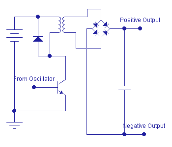
There are many ways of shifting power supply from one level to another. The circuit on the right is one of the simplest, and most efficient.
An oscillator with any waveform (preferrably a square wave) is fed to a common-emitter transistor configuration, whose collector is connected to the primary of a transformer.
The rectified voltage from the secondary of the transformer will be proportional to the power supply at the primary. The ratio of the number of turns at the primary and at the secondary will determine the magnitude of the rectified voltage. It is also possible to provide a voltage regulator at the rectified DC section, if this is called for.
Note. A suitable way of limiting current to the transistor must be implemented in order to prevent overloading of this transistor. Also note that the iron core of the transformer should be able to handle the harmonics that will be generated by the fast-rising and fast-falling voltage inputs.
|

|
|