| 1 | j mella / a pangilinan |
| 2 | c rivera / j simon-king |
| 3 |  |
| 4 | a sevilla / s vy / j nieva / k talamayan |
| 5 | a rebong / s sy / e tan / e salvador |
| 6 | back to current updates page |
| back to top (j mella / a pangilinan) |
|
| back to top (c rivera / j simon-king) |
|
| back to top (s chua) |
|
1 2 3 4 5 6 7 8 9 back to top page 01 
|
|
1 2 3 4 5 6 7 8 9 back to top page 02 
|
|
1 2 3 4 5 6 7 8 9 back to top page 03 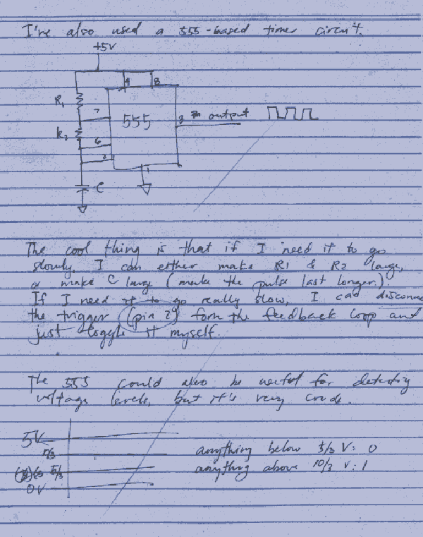
|
|
1 2 3 4 5 6 7 8 9 back to top page 04 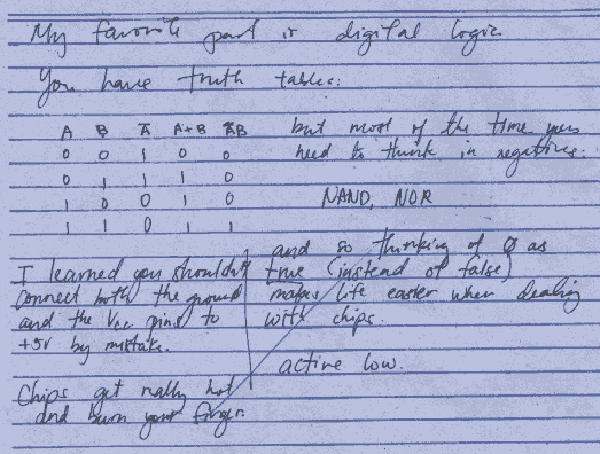
|
|
1 2 3 4 5 6 7 8 9 back to top page 05 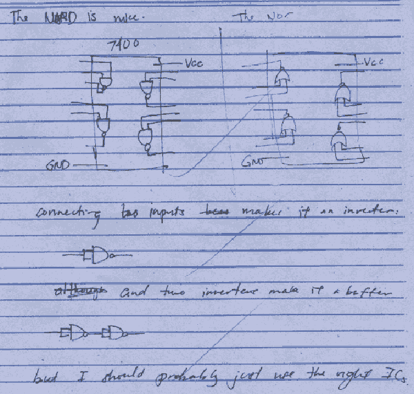
|
|
1 2 3 4 5 6 7 8 9 back to top page 06 
|
|
1 2 3 4 5 6 7 8 9 back to top page 07 
|
|
1 2 3 4 5 6 7 8 9 back to top page 08 
|
|
1 2 3 4 5 6 7 8 9 back to top page 09 
|
| back to top (a sevilla / s vy / j nieva / k talamayan) |
|
|
Power Supply
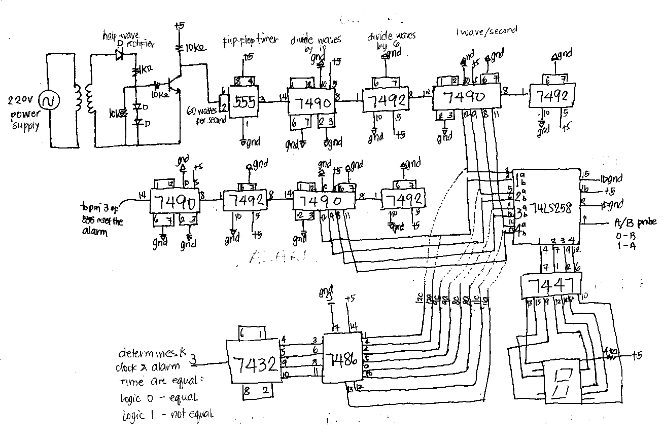
As the name implies, the power supply provides the voltage for the circuit. Transformer The transformer gathers the amount of voltage needed by the circuit. There are three types: step-up which increases the voltage, step-down which decreases the voltage and isolation wherein the voltage is the same. In the circuit, the transformer steps down the voltage from 220 V to 120 V. Rectifier The rectifier converts the voltage from AC to DC. In the circuit, a half-wave rectifier was used. The two diodes and resistors that follow are circuit protectors. If the diodes are opened, the voltage flows to the transformer directly however if it is short, the voltage continues to the next diode. Transistor The transistor is a solid-state device for amplifying, controlling, and generating electrical signals. The transistors of a digital circuit are operated as switches having only two states: on and off. They are combined in a manner to perform logic, arithmetic, and memory applications. Explanation for the 555, 7490, and 7492 (clock and alarm) The 555 is a timer which accepts DC voltage and outputs it in a fluctuating manner, thus representing the tick tock movement of a clock. In this particular setup, we have what we call a flip-flop. It basically determines whether we have logic 0 or 1. Sixty waves per second are produced by our power supply and this enters the timer. When the voltage is 2/3 of the original, the pin 6 of the 555 will sense it and tell pin 3 that we have logic 0. On the other hand, when we have 1/3 of the original voltage, pin 2 will sense it and tell pin 3 that we have logic 1. And because we have 60 waves per second, we have alternating logic 0's and 1's. Meaning the two diodes will alternately light for 60 times per second. To move on we go to the 7490 chip. This is a counter that divides the input waves by 10. And because it is a counter, it saves the info stored to it and increments it as new waves enter. Thus we can have 1, 2, 3, and so on seconds. In the 7492 counter , the waves are further divided by 6. Thus we now have a one to one relationship. We have one wave per one second. Thus, we now have a clock timer which resembles that of our normal time. The diodes will light alternately every second. We have now achieved our clock timer. Another set of counters is constructed with the same connections as of our clock. This would serve as our alarm timer. We want this alarm to be in line with our clock so we set it the same way in order to have one wave per second. The 74LS258A as a data selector In the circuit, the 256 is connected to the 2nd et of 7490s from the clock and the alarm. The inputs are placed in the 258’s four identical 2-input multiplexers. The Io inputs are selected when the select input is low and the I1 inputs are selected when the select input is high. In result, when the IC “selects” logic 0, the input read is that of the alarm and selects logic 1 when it reads the input from the clock. The 258 is connected to the 7447 which decodes the output of 258. The 74LS47 as a segment decoder This part of the circuit accepts four lines of BCD input data from the 258. It generates their complement internally and decode the data with seven AND/OR gates. Each segment output is guarantedd to sink 24mA in the ON(Low) state and withstand 15V in the OFF(HIGH) state. The 7447 is connected to to the display which serves as a visual counter. |
| back to top (a rebong / s sy / e tan / e salvador) |
|
- 741 is an operational amplifier
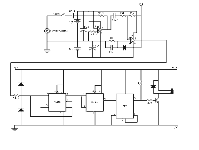
- the basic circuit of an Op-Amp is made using a difference amplifier having two inputs and at least one output - we used the chip as an inverting amplifier meaning, its output is obtained by multiplying the input by a fixed or constant gain, set by the input resistor; the output is inverted from the input - it is called inverting because the input voltage is connected to the opposite polarity output - The 2 diodes in this part of the circuit act like a limiter wherein it limits the incoming voltage to 0 to +5 from the -12 to +12 of the analog circuit. - The 555's input sensitivity aids the slow pulsating input to a faster one. The 2 555 chips in this circuit act like an interface for the transition of analog to digital circuit. It converts the slow high rising pulse of the analog circuit to the fast high rising pulse in order to cater the requirements of the 7474. - In order to drive the 7474 chip, it needs fast high rising pulse. - The 7474 is a flipflop chip. It goes to logic 1, then 0, then 1, and so forth. The 555 controls the transition of the 7474. |
|
|
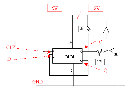
- The output of the 555 will be inputed to pin 3 of the 7474. When Q bar or not Q (pin 6) is high, D (pin 2) is high. Q, on the other hand follo,ws D. So when D is high, Q will be high also.
- Since Q bar is the contrast of Q, it will become low. When Q bar is low, D will also be low and in turn, Q will also be low. When Q bar sees that Q is low, it will go high and D will also be high. Q, in turn, will also be high. The cycle goes on and that is why it is called a FlipFlop chip. - The voltage source for the 7474 is 5V. Giving the chip a higher voltage might toast it. - For the transistor, however, the voltage source is 12V. The resistors are placed to protect the transistor from getting too much voltage. - Moreover, the diode acts as a limiter, the protector of the relay. - The transistor plays the part of a switch. It turns on the relay, which also plays the part of a switch. The relay turns on whatever appliance is connected (with proper connections and voltage computations of course). capacitor - concentrates electric field, lessen sensitivity, "choosing" the distinct sound, stabilize the sound reception reason for connecting two 741's Constant gain multiplier - provides precise gain of amplification. Multiple stage gain - to produce more gain; over all circuit gain is bigger because of the multiple stages it went through Potentiometer - to adjust the gain and the feedback easily |
|
back to top