Back to PS 141 INTRO Page

  PS 141 - Section A

A2 Antonio Maria R Bautista
A2 Maria Esperanza Fatima F Ortile
A4 Jan Benedick Asturias
A4 Kendrick Timothy Huang
A5 Perry Pe
A5 Jarell Mallari


A6 John Philip Posadas
A6 Kimberly Ong
A7 Randolph Espinosa
A7 John Hardey Loang
A8 Vanessa Gonzales
A8 Kenneth Flores
 
 
  PS 141 - Section B

B2 Esmee Siy
B2 Celilia Hung
B3 Mia Montayre
B3 Jairus Aragon
B4 April Rey
B4 Mark Lihan


B5 Adrian Rodriguez
B6 Enrique Perez
B6 Ramon Mejia
B7 Ryan Pachayasatierkul
B8 Jun Danganan
B8 Ramon Caguion


PS 141 A - Group 2

Antonio Maria R. Bautista              February 4, 2004
Maria Esperanza Fatima F. Ortile

What have we learned from Electronics?

Looking back on our first days in the subject, we realize 
that we didn’t know what to expect. So many questions 
had formed in our mind. Would our experience be as bad 
as our previous subject, Physics 21? Would our teacher 
be a terror teacher, or a kind teacher? Would we actually 
learn a lot of things while taking up the course? We 
entered the classroom, armed with an open mind and a 
thirst for answers. 

Now that we’re approaching the end, we guess that it’s 
safe to say that we learned two very important things: 
first, yes, it’s ok to make mistakes.  And second, yes, 
things do break when you make mistakes; but that’s ok. 
You learn from those mistakes, and then make your 
project better. We learned how to use so many things that 
we never knew existed before. I, for one, always thought 
that all ICs were the same; that they all had pins and 
connected so many wires.  But it was more than that. It 
wasn’t just a little computer; it was a tool in creating 
works of art, our canvases our breadboards, and our 
masterpieces, our projects.

We learned how to create simple circuits by connecting 
different gates, ICs, resistors, capacitors, and a power 
supply. We also learned how to count up to one specific 
number using binary language. We learned about how to 
use the ne555 timer chip properly in making our circuits 
count, and how to make something happen from that counting. 
That something we did with the 555 chip was to make lights 
blink. We learned how to connect and, nand, or, and nor 
gates together to create a desired effect. We learned how 
to use these ICs properly, and learned to judge what IC 
should and should not be used for certain cases. We learned 
that sound comes merely from fluctuating energy.  We 
learned the value of hard work, and the joys that came with 
it. We learned that electronics could be enjoyable, even 
with all its complications and frustrations.  And most of 
all, we learned that Electronics is not just something we 
do for the heck of it; instead, it is something we do in 
order to understand our world better, and to have fun while 
doing it.
 

PS 141 A - Group 3
 

PS 141 A - Group 4
 

PS 141 A - Group 5
 

PS 141 A - Group 6
February 4, 2004

Ong, Kimberly
Posadas, John Philip

Things we’ve learned:
  • How to trouble shoot (a little, at least).
  • How to appreciate neatness in our work.. It’s easier to look for mistakes that way.
  • How to build a simple counter.
  • Two heads are definitely better than one.
  • There are easier ways in solving a problem. Trying the simplest solution first is always better.
  • Sometimes, common sense is enough to solve a problem that looks so complicated
  • Never panic when something goes wrong. Keep cool and stay focused and calm
  • It never hurts to ask help from a friend
  • Devices that look so complicated may actually be simpler than what it is.
  • Follow the instructions slowly but surely.
  • It is always best to have a schematic diagram ready so that when other people can’t understand what you are doing with your electronic devices, they could at least understand what’s going on.
  • It feels good to solve a bug/problem by yourselves.
  • In electronics, things will always work out logically (abstract ideas) but may not always work when it involves the actual devices to be used (concrete/put into practice). Some assumptions may have been overlooked causing things that should happen not to happen.
  • The most important thing to remember when doing a project/task/activity is to have fun.
  • Enjoy what we are doing to learn it by heart.
What we want to learn:
  • Anything as long as it is fun! There’s no complaining in things that we enjoy doing. When you learn how hard it is to make a simple gadget, you learn how to appreciate more complicated things. It’s really tricky to think of how to utilize a couple of IC’s to make it work magic but then again it is fun and rewarding when you’re finally able to make it work. Large-scale schematics may seem to freak us out at first glance, but it can be done by doing the task part by part, little by little. Also sometimes, it is best to observe carefully first before ranting about things not going so well—maybe all the circuit needs is a little check of the basics.
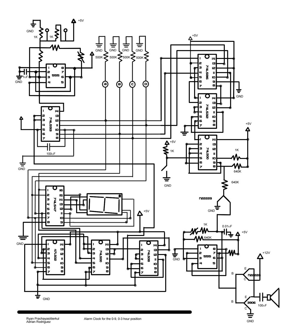
 

PS 141 A - Group 7
John Hardey Loang
Randolph Espinosa

What have we learned?

In the first day, we were firstly taught of having no 
judgment against others.  This helped a lot in doing 
experiments because you will not have to worry of others 
making assumptions.  You can do different kinds of 
experiments with the many materials available.

While in the lessons, we learned of the uses of light-
emitting diode (LED), resistors, capacitors, integrated 
circuits (IC) and potentiometer in the first few days.  
That time, we were building 2 LED that alternately blinks.  
Then we built LED that counts using binary digit (4 LED).  
Then the “8” LED, counting from zero (0) to nine (9).

Then we tried to ‘limit’ up to how high the IC will count.  
In our group, our LED needs to count up to 9.  While other 
groups had to make the clock count up to two (2), 
three (3), five (5) and another nine (9).

After this, we attached a few more parts – transistors, more 
IC’s and a speaker.  In this new upgrade, we tried to make 
an alarm.  The alarm will sound indefinitely.  Then, the 
alarm “system” was again upgraded into a real alarm.  It 
will sound in a specific number shown in the “8” LED and 
stopping when the next number is shown.

Finally, we tried to connect all six bread boards to create 
a clock with 23?59’59”.  But the problem is how to regulate 
the beats of the second hand into real seconds.  We then 
used the electricity from MERALCO to regulate the seconds.

The parts we need in this experiment is a transformer.  We 
then, after connecting the proper IC’s, connect this new 
bread board with the clock.  After several troubleshootings, 
we were able to regulate the beats.

In the end, we created the clock that counts properly!
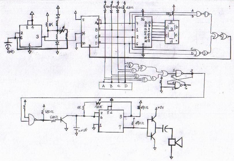
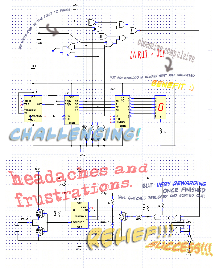
 

PS 141 A - Group 8
Vanessa Gonzales and Kenneth Flores

Every Wednesday afternoon, we find ourselves stuck in the 
lab for four straight hours.  Aside from having a good 
time with our blockmates in an air-conditioned room all to 
ourselves, it also means four hours filled with many 
moments that serve as opportunities to learn… whether 
electronics-related or not.  

After a number of weeks working on our circuits, we finally 
succeeded in merging all our breadboards to produce a working 
24-hour digital clock.  From the basic blinking lights, to 
four LEDs working like bits that count 0-15, to sound alarms, 
and finally to an actual clock… what else can reward you with 
such a feeling of fulfillment?  

Of course, we do not pretend to know every technical detail 
of every corner of our breadboard.  But the important thing 
is, we know how things should work – which LED should light up, 
when the alarm should produce a sound, at what number should 
the counter reset, etc… Knowing all of these enables us to 
figure out how to deal with problems, where to trace them, and 
how to troubleshoot.  It’s a process we find ourselves doing 
most of the time, and the repetitiveness helps us in improving 
our skills in solving the problems.    

Halfway through the course, we find that the time we spend 
poking through the colorful mix of wires, ICs, and LEDs gives 
us countless nuggets of wisdom.  If anybody out there comes to 
us and asks us what Ps141 taught us, these are the little but 
meaningful things we’ll say to them:

Have fun!  Work is easier to do when you have a smile on your 
face.

Find a way to memorize the resistors’ colors.  Even weird 
acronyms help!  (BBROYGBVGW = Bad Boys Rape Our Young Girls, 
But Violeta Gave Willingly.)

Even the most complicated devices work on the basis of 
simpler and more basic principles.

If you really do the lab work, you’ll find out how to 
construct a working 24-hr counter; what an oscillator is 
for, 555; what a counter is for, 74LS93; what a black box 
is for; how to use gates; how to configure a seven-segment 
display; how to construct an alarm; how to make an 
amplifier; how to create ticking sounds from bits.

Aside from aesthetic purposes, straightening out the wires 
makes it much easier to find out where the bugs are.

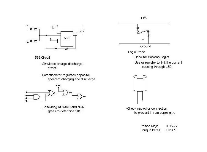
A logic probe makes troubleshooting so much easier.

Nothing beats common sense.

Be patient.

Working with a partner really helps… a lot.

Never give up on your breadboard.  Just give each IC a 
little tap and say, “C’mon, my friend… be good!”  And then, 
continue working on the problem.

If all else fails, ask for help.

Help each other.

Don’t be afraid of asking questions.  This is how you 
actually learn.

Transistors, ICs, and soldering irons can hurt you when 
they’re burning hot.  Be cautious.

Be responsible for the devices that you use in the lab.  
Otherwise, thou shall not get your lab breakage refunds.  

Even if it’s easier to accuse others of sabotaging your 
work, most of the time, the problem is actually caused by 
your own carelessness.

Working step-by-step means you’ve got a better chance of 
having an organized and working breadboard.

Working on more recent additions to your breadboard 
doesn’t mean you can forget what you did in the beginning.  
Chances are, you’ll have to backtrack to the previous 
parts of the circuit to solve current problems.

As we’ve mentioned above, we are only halfway through the 
course.  There’s still a lot more to learn, and there are 
some things we’d still like to do if given the opportunity.

For instance, it would be cool to tamper with a PC’s 
motherboard and see how stuff works inside the CPU.  (We 
are CS students, after all.)  This may help us understand 
how simple devices are used together to create a more 
complex device just like a PC.

It’s also nice to work with sensors that respond to external 
stimuli, like light, sound, or movement.  For example, 
something that uses a light sensor IC, similar to the light 
posts around Metro Manila.


PS 141 B - Group 2
Esmee Siy 
Celilia Hung 
 

PS 141 B - Group 3
Mia Montayre 
Jairus Aragon 
 

PS 141 B - Group 4
April Rey
Mark Lihan


What are they and what we have learned?

Resistors 
    - they have four colors.  Each colors represents a 
    number or place value depending on the order of that 
    color. 
    - The measurement of a resistor is in ohms and it can 
    be derived from its colors.

Capacitors
    - Makes a limit to the flow of current
    - Always connect the negative side to the ground and 
    positive to the +5 volts. If not, the capacitor will 
    explode so we should be very careful.
	  
Potentiometer 
    - regulates the flow of current
    - makes the blinking action either faster or slower 
    also adjusts the pitch of the sound of the speaker
LED	
    - the light
Circuits
  555 
      - allows alternating high ("1") and low ("0") current
      - "1" is between 2.4 to 5 volts
      - "O" is between 0 and .8 volts
  74xx93 
      - allows 4-bit binary counting 0000 - 1111 or in 
      decimal 0 - 15
  74xx47 
      - synchronizes the couinting action of the LCDS 
      with the clocks
      - determines until what number the clock will 
      count (but needs a black box)
  black box 
      - is a combination of 7400 (nand) and 7402 (nor) 
      - given an specific input, the will give an output 
      of logic 1, if and only if the input is that given 
      input.
  7 segment display 
      - shows a digital output of the counter 0 to 15.
      - each bit should be connected to the proper pin in 
      order to view the correct format of the number
  7486 
      - exclusive nor
      - used in alarms, similar to the black box
  2n2222 
      - have 3 pins, emitter, base and collector
  flip-flop 
      - is like a memory that contains saves 1 bit of 
      information
      - it is connected to the momentary push button 
      audio driver 
      - another 555 is configured as a variable frequency 
      oscillator
      - sound may be picked up from pins 3 or 7, as the 
      designer so chooses. 
  
Other stuff we have learned

Talk to the breadboard!

Use of binary logic with nand, nor and exclusive or

Using soldering iron and lead 

Cut wires and removes the cover quickly with a wire cutter

Short circuit happens when positive and ground are 
connected

Gates have different inputs and outputs, for example nand 
gate has pins 3, 6, 8 and 11 as outputs while a nor gate 
has pins 1, 4, 12, and 15.

Have patience and have fun!
 

PS 141 B
Group 5 - Adrian Rodriguez
Group 7 - Ryan Pachayasatierkul
What we have learned in our Physics Lab...

Instead of finding the laboratory boring, it was the other 
way around. 

Here, we learned the possible and real-life applications 
of the electronic components we learned in the lecture part 
of the subject. 

We learned the different applications of the different 
components that make up a circuit. We also got to use the 
different ic chips for setting the clock in our project. 
We initially made a simple blinking light where we used 
a binary timer called a 555 chip and some LEDs and a few 
wires and resistors. Later on, the lights evolved by adding 
another chip and more LEDs and a LED counter that counts 
from zero to fifteen. We used various gates that when used 
in conjunction with other gates would produce a different 
max number before resetting. And after adding more gates to 
the board, we added another 555 chip and this time it was 
configured to produce sound. By combining the sound to the 
clock along with the rest of the other gates, we were able 
to form a functioning timer with a manually programmable 
alarm. And finally we combined all the timers to form one 
big clock with alarm (similar to how voltes v was created?) 

We also learned some tidbits in connecting the pieces of the 
circuit. Like a capacitor should be correctly plugged in, 
else it would cause the capacitor to overheat and explode. 
Others like making a change in how a resistor is used would 
determine an LED's brightness. And most importantly, the 
topic of making, finding, and preventing short circuits in 
circuitry. 
 

PS 141 B - Group 6
Ramon Mejia              5 February 2004
Enrique Perez            Engineer Calasanz

Most students, when asked about what learning within the 
confines of a classroom is, say that it should include a 
lot of studying, quizzes, tests, homework and other 
‘measures’.  Yes, sometimes learning is just restricted 
to these activities, all mechanical and clerical. But 
there are a few exceptions, and electronics is one of them.

We can say that we have acquired our learning through 
three processes. First off, the implementation of 
different kinds of circuits has contributed to our 
knowledge of electronics.  Circuits, whether written on 
the blackboard or of our own design, allowed us to see 
the capabilities and limitations of electronics, and 
their practical uses without memorization and pure 
objective learning. Some of our implemented circuits 
include:

The Logic Probe. 
     This is simple yet fundamental circuit has showed 
     us how current flows, and its importance in a 
     circuit's function. By connecting the ground to 
     various parts of the circuit, we can cut power 
     off one LED and determine if the ground is connected 
     to a high or low current.  It has also invited us to 
     investigate what are the functions of a resistor, 
     and why a LED must have one resistor within a series 
     connection. We have learned that if we do not limit 
     the current travelling through an LED, it will burn 
     out.  Thus we understood positive and negative logic 
     and how it should be used in electronics.  We, as 
     computer science students, use Boolean logic to 
     implement our programs, and this exercise and its use 
     in debugging has greatly helped our logic and 
     thinking.

Introduction to Chips: 

555. We learned the characteristics of a chip through 
the use of a 555, a chip that simulates a charge-
discharge effect and makes the current go high and low 
alternateley.   Every chip should have a connection to 
a power source, and the TTL series consumes about 5V.  
One of its pins must also be connected to low voltage, 
to let the chip be functional.  another characteristic 
of the chip is that when nothing is connected to a pin, 
by default the chip's pin assumes a high value.  When 
the 555 was connected, its charge-discharge action 
alternates high and low power, and thus alternates the 
lights of the logic probe.

Binary and Decimal Counting: 74xx93 and the 7-Segment 
Display. 
     Through the use of the 74xx93, we were able to make 
     our circuit 'count'. Using the binary system of 
     counting, the LEDs connected to 4 of its pins showed 
     how counting was done.  This has made counting using 
     0s and 1s like second nature to us. When combined 
     with the 7-segment display, we were able to see the 
     decimal equivalents of the binary numbers the LED 
     displayed. To do this, we use the 74xx47. It converted 
     4 bits of binary numbers, which went from 0 to 15, to 
     7 outputs which light up each of the 7 segments and 
     showed the decimal equivalent.

Circuit Design: 

Gates. By giving us the freedom to design our own gate 
     implementation, we were able to tap on AND and OR 
     gates with our own level of understanding. This 
     meant that we must increase our interest to gain 
     more ideas on how to implement it, and making us 
     learn in an enjoyable way.  We were assigned to 
     design a circuit so that when it reaches a certain 
     binary pattern, say 1010, it sends a high signal to 
     the reset pin of the 74xx93, which in turn will 
     reset it to 0. This started conversations and 
     brain-storming, as we eventually pulled the feat 
     off. 

Alarm. By connecting our newly designed 0 to 9 clock, we 
     now connected it using various NAND gates to form an 
     alarm. By using a series of NAND gate implementations 
     that seemed weird, we finally understood the 'reset' 
     button and how it works with the alarm. After this, 
     a 2n2222 was used to buffer the circuit.  A speaker 
     supplied with 12V of power was connected to a 555, 
     and 2 pieces 2n2222 served as a vital part in making 
     this analog part of our circuit connect to the 
     digital part of the circuit. Although very complicated, 
     we are slowly learning why buffering and conversion 
     from digital to analog is important, and more debugging 
     has given us a lot of experience and appreciation to 
     electronics.

Yet more than the weekly exposure to various circuits, chips, 
and devices, we have also learned through the process of 
implementation. In our class, nothing is spoon-fed. Yes, 
there are times when we could not understand a design or 
track down a bug, but after asking for help we learn to work 
on it ourselves.  This type of training has taught us 
patience and perserverance in implementing and debugging 
circuits. We slowly see past the complexities of the circuit 
and understand more and more about how each section and 
component works.

Finally, if there is anything we never imagined an 
electronics class could teach us, it is to think freely. 
To come up with our own ideas, to have the freedom to 
wire the circuit in our own way, and to teach us how to 
figure out bugs and gate variations all have given us fun 
and learning apart from books and unforgiving teachers.  
As the engineer said to us when asked if our design on 
paper was correct, "Put it on the board and try it out. 
If it doesn't work, then fix it. Talk to your circuits. 
They might answer back." Also, to try out new things like 
implementations using the computer and other 'crazy' and 
'unthought of' ideas taught us the joy of free thought and 
speech. Freedom to experiment our queries and to question 
the why and how of circuits sparked interest and enjoyment. 
For us, this is a very valuable lesson, more than any 
other lesson in our electronics textbook.
 

PS 141 B
Group 5 - Adrian Rodriguez
Group 7 - Ryan Pachayasatierkul
What we have learned in our Physics Lab...

Instead of finding the laboratory boring, it was the 
other way around. 

Here, we learned the possible and real-life 
applications of the electronic components we learned 
in the lecture part of the subject. 

We learned the different applications of the different 
components that make up a circuit. We also got to use 
the different ic chips for setting the clock in our 
project. We initially made a simple blinking light where 
we used We made a binary timer called a 555 chip and some 
LEDs and a few wires and resistors. Later on, the lights 
evolved by adding another chip and more LEDs and a LED 
counter that counts from zero to fifteen. We used 
various gates that when used in conjunction with other 
gates would produce a different max number before 
resetting. And after adding more gates to the board, we 
added another 555 chip and this time it was configured to 
produce sound. By combining the sound to the clock along 
with the rest of the other gates, we were able to form a 
functioning timer with a manually programmable alarm.  
And finally we combined all the timers to form one big 
clock with alarm (similar to how voltes v was created?) 

We also learned some tidbits in connecting the pieces of 
the circuit. Like a capacitor should be correctly plugged 
in, else it would cause the capacitor to overheat and 
explode.   Others like making a change in how a resistor 
is used would determine an LED's brightness. And most 
importantly, the topic of making, finding, and preventing 
short circuits in circuitry. 
 

PS 141 B - Group 8