Remote Video Surveillance using Radio ControlChristian Lazo, Brey Lee, Jenard Mendoza, Pocholo Pasicolan, Melissa Rellosa Tristan Calasanz and Carlos Oppus Abstract—The project aims to build a simple but functional remote surveillance device using available RC appliances. In essence, a wireless camera was mounted on an RC toy tank to serve as a functional remote video surveillance device. The 27 MHz remote control toy tank is responsible for motion on land and a 2.4 GHz wireless camera provides for off-location video. In addition, these two wireless devices were interfaced to a computer so that the movement of the tank and the viewing of the off-location video were handled by a software program. In more detail, the mechanical switches of the remote control were replaced by mechanical relays, which are connected to the parallel port of the computer. A circuit was used to electrically isolate the parallel port from the remote control for safety purposes and at the same time, step up the low power output of the parallel port so that triggering the relays will not be a problem. A Visual Basic program was responsible for triggering the correct combination of relays for the desired tank motion. A TV tuner card was the interface for the video signal from the camera and this signal was also used by the Visual Basic program. Essentially, the program displays what the camera sees and waits for keys to be pressed that would move the remote device. In addition, the group further increased the effective controlling distance between the operator and the remote device by accessing the software control program through a LAN connection.
I. INTRODUCTION Unmanned surveillance is of particular use when investigating situations which might pose risks to human lives or in certain circumstances wherein survey-related tasks done directly by man prove to be too cumbersome. Wireless communication via radio frequency is a common mode for controlling remote surveillance devices since the operator is not limited by line of sight The parallel ports were originally developed by IBM as a way to connect a printer to the PC, hence the more common name, printer port. It is an inexpensive yet powerful platform for implementing projects dealing with the control of real world peripheral devices. The printer port has eight TTL outputs, five inputs and four bi-directional leads and it provides a very simple means to use the PC interrupt structure. (Anderson, 1996) This project interfaces a remote control toy tank, which is readily available in the market to the parallel port of a personal computer which results to the transfer of manual control from the ready made RC circuit to the computer user. The tank is fitted with a wireless camera, further expanding the use of the remote control tank from that of a toy to a remote spy video surveillance. The camera, which is also interfaced to the computer, provides for off-location video capture and streaming. In addition, the functions of the two computer interfaced devices were handled by software programs
II. STATEMENT OF THE PROBLEM The ports of a PC can control a wide range of external devices with different applications. Only by interfacing one of these devices to the PC can one realize the port’s versatility. Remote surveillance is an application of one such device. Primarily, it involves control of movement and video feedback. However, controlling movement entails manipulating a combination of different actuators, and video feedback involves reception of steams of data. Thus, questions such as, what ports to use, how data is send/received, and what external electronic circuitry are needed, arise. A. Objectives The objectives of this project can be seen as a threefold goal. The first part of the project aimed to interface the remote controlled tank to the personal computer via the printer port. The second part of the threefold goal of the group was to be able to mount the wireless video camera to the tank and interface the camera to the personal computer. In this way, the tank is controlled via the printer port and live footage, which could be viewed live or captured from the camera positioned on top of the tank, could be seen as the tank travels. The last aim of this project was to expand the range of controllability of the remote controlled tank through the use of Local Area Network (LAN). B. Materials and Methodology The main plan behind the project was to use the remote control device that came with the vehicle, and "hack" it. Necessary components were then added and linked to the remote control. The user inputs into the PC his/her desired commands through pressing designated keys and the software sends out corresponding signals into the parallel port. The signals sent to the parallel port are then transferred to the relay circuit where it is translated into on/off switching. The relay circuit is then connected to the remote control circuit and there, the decoding of the switching pattern happens. The tank subsequently moves correspondingly. It is important to note that since the camera has its own receiver and transmitter independent of the tank, it sends out images to the PC even if the tank is not in motion. C. Scope and Limitations In view of the fact that the portion of the project that is directly focused on interfacing is the remote control circuit, bulk of the hardware modifications which the group implemented, was done on this module. The group used pre-fabricated materials and equipments as such, any inherent flaws or limitations of these materials are beyond the group’s concerns. Among the limitations are the following:
In addition, it is beyond the scope of this project to delve into the inner workings of RF transmission and reception theory. Two separate software were used for controlling the tank and providing for the video capabilities of the Remote Video Surveillance. Windows NetMeeting ® which has no stand-alone remote video streaming capability, was used to provide remote video streaming The custom-made control software can only record in AVI format, consequently, video cannot be recorded while the unit is being accessed over a TCP/IP network. III. HARDWARE DESIGN A. Relay Circuit
Figure 1. Relay Circuit
The relay circuit shown in figure 1 was used as the switching circuit. The signals coming from the computer, passing through the printer port goes to this circuit, which is then connected to the remote control circuit of the tank. The user could then be able to activate the various directions of movements of the tank and control it to its desired motion even in the absence of the manual levers of the original remote control device. In effect, the entire relay circuit is composed of seven of this relay circuit, corresponding to the 7 basic tank actions. Details on this part are discussed in the Remote Control Circuit. One might ask why the signals coming from the printer port are not tapped directly to the remote control circuit instead of bypassing it to the relays where switching action still takes place. There are two reasons for this. The first reason is due to the need to protect the computer from any unnecessary fluctuations or changes in the voltage/current in the external circuit, hence the need for an opto-isolator. Note also that there are two separate power supplies connected to the circuit. The first powers up the opto-isolators while the second powers up the relays. This ensures a complete isolation of the printer port and ultimately, the computer from the rest of the switching and remote control circuit. The second reason is for stepping up of the low power output of the parallel port. This minimizes the errors in movement of the tank, which could happen if the signals coming from the computer were not completely defined.
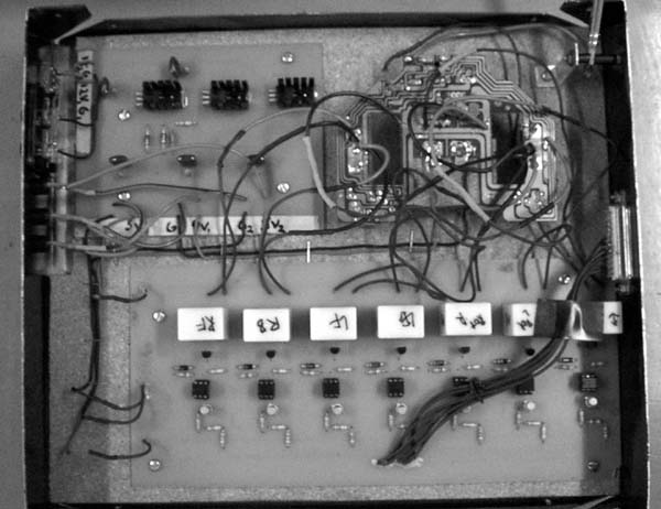
Figure 2. Actual PC to RC interface circuit
B. Mode of Operation A relay is an electro-mechanical device that acts as a switch. The construction of the device is such that it has 5 external pins: 2 of these are connected to an internal coil, one normally closed, one normally open pins and the fifth pin, generally known as the ‘common’, is the pin that determines what is normally open or closed. The normally closed pin is the pin that is in contact with the common pin when the voltage across the relay coils does not reach the triggering voltage requirement. Inversely, when enough voltage is placed across the relay coils, the normally open pin would be the one in virtual contact with the common pin. Only one of the normally open or closed pins can be in contact with the common at an instant. For the project, the ‘common’ and the normally open pins were utilized as they were connected to the two points of the contact switches in the actual remote control circuit. In effect, when the voltage across the relay’s internal coil reached the triggering level, the common becomes connected to the normally open pin. This pin is connected to the movable lever, which is drawn to iron core at the center of the coil, at the time that the magnetism produced by the coil develops enough force to overcome the tension on the spring. Hence, the switching action of the remote control levers may be simulated. Since seven (7) of these are used in the project, depending on the signals sent by the computer, it is possible to control all the directions and motions specified by the original remote. When the circuit is at logic "1" at the entry point between the parallel port and the circuit, it is in the off state. The logic "1" in the data stands for the parallel port being set to around 5V. It is important to note that the normal operation of the circuit is active low, such that the control word sent by the software through the parallel port is inverted. In this case, there would be no potential difference between the entry point and Vcc. Hence, there would be no potential difference across the internal LED of the opto-isolator. Since the no light is emitted within the opto-isolator, the phototransistor would not be triggered leaving an open connection between the emitter and collector of the said phototransistor. There will be no potential difference between the collector of the phototransistor and ground. Consequently, no current will flow through the base of the 2N2222a, which will not allow the transistor to reach its triggering voltage across its base and emitter. In turn, the collector and emitter of this transistor will also have an open connection. In this condition, there would be no voltage drop across the relay coil because Vcc went to the emitter-collector open connection. Hence, the relay is not triggered, maintaining the same state. When the circuit is at logic "0" at the entry point, there is a voltage drop between Vcc and this entry point (approximately +5V), which produces a current flowing through the left-side of the opto-isolator (side connected to the PC). A voltage drop across the internal LED of the opto-isolator is then produced to activate the phototransistor. This results to the saturation of the phototransistor, shorting the its emitter-collector nodes. Current flows downwards from the Vcc to the base of the 2N2222a transistor. This current generates enough voltage between the base-emitter nodes of this switching transistor, activating it. A minimal emitter-collector voltage drop is produced, which leaves enough voltage difference between the coils of the relay. Thus, the relay is triggered and the normally open pin is magnetized to connect with the common pin. This imitates the actual pushing of the joysticks of the remote control to switch that generates the movement of the RC vehicle.
C. Opto-Isolator
Figure 3. Opto-isolator The opto-isolator is a special IC used to electronically isolate two components. The connection on side a does not affect side b. It consists of a light emitting diode and photo-transistor. Normally, the LED is not emitting and the photo-transistor is effectively an open circuit. When a voltage drop is applied across the LED, it emits light within the opto-isolator IC. This light is absorbed by the photo-transistor, thereby saturating it, then a short circuit would occur. D. Tank Mechanical Components & Remote Control Circuit A commercially available RC toy tank was acquired. The mechanical features of the tank consists primarily of the tread control, turret swivel and barrel movement mechanisms.The operations of the toy tank simulate that of a real tank. Its motion is dictated by two threads. Each thread is driven by a DC motor. The two motors are bi-directional in the sense that the tank is capable of switching the polarities of the application voltages across both motors, thereby changing the direction of rotation of the motors. Depending on how the motors are configured, the tank can move forward, backward, rotate in place, and move tangent to the left and right direction.
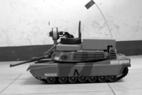
Figure 4. Camera mounted on RC tank
In addition, the tank has the capability to swivel its turret to the left and right. This action is controlled by a third bi-directional motor. Because of this feature, the camera can be mounted directly on top of the turret having the ability to "look" left or right. Finally, the barrel’s motor rotates a knob that is connected to a lever, which in turn moves the barrel so that, when the knob’s vertical position changes, the barrel moves up and down periodically. An attachment was made to translate this is mechanism to the camera. However, the rotation of this fourth motor is limited to one direction. As a consequence, when the camera overshoots its desired angle, the next cycle would have to be repeated until the desired angle of the camera is attained.
Table 1. Tank Movement & Control Combinations
The tank features eleven types of movements. These tank movements are a result of combining the seven basic features of the tank (Table 1). In effect, these seven basic tank control movements were each assigned an output bit from the parallel port (Table 2).
Table 2. Tank Control and Assigned Bit
Table 3. Tank Control Word vs. Tank Movement
The application programmed for this project sends out a control word each time the user executes an action by pressing a key. The control word is sent to the relay circuit. Each relay corresponds to a bit in the control word. The bits are individually tapped to designated portions of the remote control circuit. A logic ‘0’ means that no action is to take place but a logic ‘1’ means that an action is to be executed.
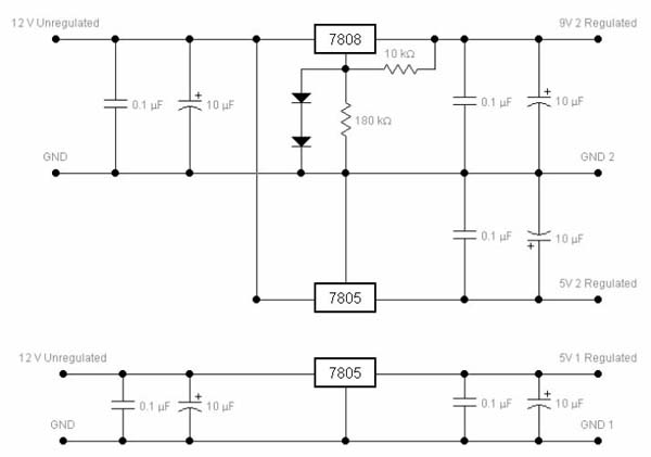
E. Voltage Regulator Circuit A voltage regulator circuit was constructed in order to consolidate into one locality all the power sources for the various circuits of the controller interface. Since only 12 V and 9 V sources are to be used for the remote control interface, the group found a way to tap onto these power supplies and obtain the proper voltages needed for the circuits of the project.
Figure5. Voltage regulator schematic
F. Tank Circuitry The tank receives radio control signals from the controller via radio interface. The signals generated have a 27 MHz carrier signal. The antenna receives this signal and the demodulator tuned into this frequency extracts the control instructions from the transmission signal. A decoder will then interpret these instructions and relay them to the individual driving circuits for the various motors. IGBT (Insulated Gate Bi-polar Transistors) provide the switching function for power to be transmitted to the tank’s motors. The motors convert electrical power into mechanical power to enable the tank to move in accordance with the instructions being transmitted by the control device.
IV. SOFTWARE DESIGN The Software design consists of three modules: the Control Module, Video Module, and the LAN Module. The Control Module implements the main server and control of the tank. It generates the bits to the main computer’s parallel port that interfaces with the Tank control black box. The Video Module connects to the video capture card of the computer that interfaces with the wireless video receiver. The wireless camera is mounted on the tank. The LAN module allows for the remote control of the tank’s movement by a computer connected via LAN to the main control/server. The client can access the tank control using a Client window and the camera feed is accessed via Windows Netmeeting.
Figure 6. Overview of Interfacing
A. Control Module The remote control is implemented using a window generated using Microsoft Visual Basic. The window consists of the mini-keypad that controls the direction and movement of the tank and its turret. The camera is mounted on the tank and in effect, the control window also controls the movement and line of vision of the surveillance camera. The remote control can function using the keyboard or the mouse. A corresponding value is latched onto the parallel port until the key or the mouse button is released. Table 4 below shows the output of the parallel port and the corresponding character on the mini-keypad.
Table 4. List of Keypad Characters and Port Output
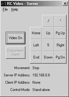
The eight bits of the binary equivalents correspond to the eight parallel port pins connected to the relay switch circuit. Since the circuit is low enabled, the zero value corresponds to the actual switch activated. Figure 7 shows the actual Control Module window; the mini-keypad is shown on the right part. The Num Lock needs to be set before one can use the numeric keypad control.
Figure 7. RC Control Window
Table 5. Shows the different options and button functions included in the server window.
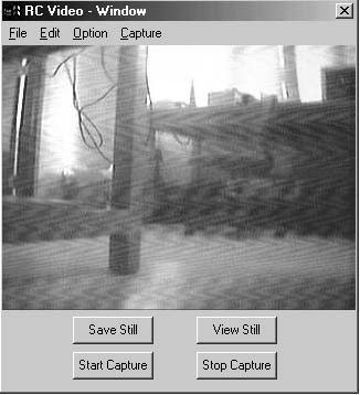
B. Video Interface Module The Video Interface module deals with the interfacing of the wireless camera with the video capture card. In this project, the video capture card used is Lifeview FlyVideoÔ 98, a television tuner. Ideally, the program should work with any video capture card, since the Video for Windows (VFW) interfaces with the video card of choice. The Video On button in the Main control window initializes the video card and opens the RC Video Window shown below. Beside it is the actual VB code for this call.
Figure 8. RC Video Window
Table 6. Shows the different options and button functions included in the server window.
The video module allows for saving of the image into bitmap and further converted into a .jpg file. It also allows for video capturing into a .avi file. The Video module also has options to set the length of recording and the video source. The Play option allows the user to view the recorded file in a new pop-up window. The View Still button views the saved .jpg file saved in the current directory. The Preview and Overlay options allow for different formats in viewing the actual feed. The Overlay option has better quality, real-time video feed but it has some limitations in the actual Save options that is compensated by the Preview options that is processed by Microsoft Windows. The RC Video Window allows for the actual feed of the camera to be saved as an actual video file (.AVI) or as frames in bitmap or compressed .jpg images in the current directory. The Save Still and View Still buttons at the bottom of the screen allows for these manipulations.
C. LAN Module The Software Design allows for the control of the tank over a LAN (local area network). The Control module is accessed via a client program shown below. However, the client program cannot directly access the video feed from the camera. WindowsTM Netmeeting is instead used to provide the video streaming facility. Since the video feed cannot be simultaneously accessed by more than one program, the main Video window must be closed before Windows Netmeeting is started on the server program, and before the video feed can be streamed to the client. The connection between the server and the client is made through TCP/IP. This allows the client program to be used over any TCP/IP network, including the Internet. The server program opens a listening socket on port 1024. The client specifies the server’s IP address to be able to connect to the server. When the client attempts to connect to the server, a window prompts the main controller if the remote client can be granted access to the control of the tank. After the server grants the client’s request, the client’s mini keypad is activated, and the client now gains control of the tank.
Figure 9. RC Video Window
Table 7. Shows the different options and button functions included in the client window.
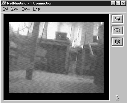
Before the client can access the video feed, both client and server must establish a Windows Netmeeting connection, with the server set to send the video. The Windows Netmeeting window is shown below.
Figure 10. Video Window as seen from Client Computer V. CONCLUSION The group was able to successfully demonstrate a simple yet fully functional remote-controlled surveillance system. Using commercially available equipment and existing programming software, the group was able to interface a remote-controlled toy tank with the PC using the parallel port. Microsoft Visual Basic was used to create a program that would decode the user’s input, send the decoded control words to the output port. This allows the user to control the surveillance device directly from the keyboard or mouse. An external opto-isolated relay circuit served as the actuator from the parallel port to the remote control. A wireless camera was mounted on the tank and hardware modifications were made for the camera to utilize the mechanical features available within the tank. Video feedback was implemented through a video capture card. In addition, the effective range of control for the surveillance system was extended by incorporating Microsoft NetMeeting, and interfacing the host PC through LAN. REFERENCES
[1] Boylestad, R and Louis Nashelsky. Electronic Devices and Circuit Theory, Seventh Edition. New Jersey: Pearson Education Asia Pte Ltd, 2000. [3] http://www.doc.ic.ac.uk/~ih/doc/par/ [4] http://www.beyondlogic.org/spp/parallel.htm [6] http://www.catalyst.com/support/tutorials/ tepintro/index.html |
||||||||||||||||||||||||||||||||||||||||||||||||||||||||||||||||||||||||||||||||||||||||||||||||||||||||||||||||||||||||||||||||||||||||||||||||||||||||||||||||||||||||||||||||||||||||||||||||||||||||||||||||||||||||||||||||||||||||||||||||||||||||||||||||||||||||||||||||||||||||||||||||||