RADIO INTERFACINGJason N. Saba and Alejandra L. Jayme Abstract - The project aims to create a hardware / software combination that is able to record broadcast coming from an ordinary AM / FM radio into a format playable by the computer (WAV file). The hardware contains circuits capable of filtering the signal gathered from the radio, and converting the signal via Pulse Code Modulation. It also contains a circuit that displays the current status of the system. The software contains a module that writes the header of the WAV file that is needed for a media player to recognize the file. The program creates 2 WAV files per recording, one using the original converted amplitudes, and one using normalized amplitudes. A module handles the visual outputs and serves as an error-checker for the system.
One advantage of digital signal processing is the ease of manipulating multimedia files encoded in digital format. Using different mathematical functions on digital data create effects that when implemented physically will require different sets of hardware. The convenience extends to the lifespan of the digitally encoded media – a format not easily affected by physical wear tear. Thus having a digital version of an analog signal – be it video or audio – proves to be quite advantageous. Focusing on how to convert real world signals to computer-readable format is a useful topic to tread on. No doubt, a lot of such converters exist already, from microphones to synthesizers, but most of them make use of the computer’s sound card to do the conversion. It is interesting to know how such a device does the conversion, and it is the aim of this project to simulate such action. An AM/FM radio presents an interesting medium where to gather audio signals. Not only does radio broadcast music, which has benefited a lot from digitizing, it also outputs all sorts of information – news, weather, general information – things that if kept recorded may prove to be valuable. Factor in the simplicity of an audio signal after removing the frequency modulation, and we have a medium that is rich and very attractive to tap into.
The project aims to convert analog audio signals coming from an AM/FM radio into its digital counterpart, while keeping as faithful to the original signal as possible. This is to be achieved by creating a special ADC hardware that is capable of converting at at least twice the highest frequency of audio waves. The PCM conversion file created is then appended with additional data to make it playable by the computer. The project further aims to provide with the hardware a control console (pushbutton) for the user to interact with the conversion, a status console (LEDs) to inform the user what is happening, and a software program that will handle all the computer-related aspect of conversion. To attain control of the ADC device, the hardware circuit is connected via the parallel port, which is being controlled by the program software. The choice of the parallel port over the serial port is simple: to achieve greater fidelity with the analog signal, high-resolution conversion in as short a time as possible is needed. Thus the hardware will pass lots of data at a single time, a quick rate that the serial port would not be able to cope up to. The status of the hardware and the converted data are passed to the computer via the status port and data port of the parallel port, respectively, while the program sends control signals to the hardware component through the control port. We look at the areas of the device that comprise the circuit. There are four basic modules for the circuit. i. The push button is the simplest of the module, and is connected to the status port of the parallel port. The debounce and edge-trigger that protects and idealize the signal sent by the pushbutton is implemented via software. ii. The LED display circuit is composed of several light emitting diodes and a buffer chip. The output display combination is controlled by the error-checking module of the software. iii. The heart of the hardware circuit is the conversion module. Its main component is the ADC1061, which is an asynchronous 10-bit converter. The configuration followed is the RD mode of operation, where the Sample/Hold pin and Read Pins are tied together.
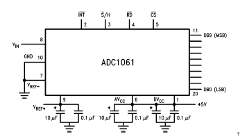
Figure 1. ADC1061 Pin out About 1.8 microseconds after pulling the said pins low, the INT pin goes low, indicating that a sample conversion is complete, and the correct data can be read from the output pins. Another conversion can be performed again. The ADC has a maximum conversion rate of 160 KHz in this mode of operation, which is much higher than the 44.1 KHz sampling rate required for audio signals. The capacitors in the figure are required to decouple the Vcc and Vref. iv. The signal coming from the radio is passed through a series of filters: a low pass filter reducing the effect of high frequency waves, making the input sound cleaner but less bright. A low pass filter removes noise and makes the input signal less bassy. The signal from the radio is gathered using a connection through the radio’s headphone port. In this way, there is no need to open up the radio, and tap through the lines going to the speakers. The program is divided into the following components: i. The calibration module, which simulates the routines found in the record module. In this sub-program, 22,050 samples are gathered from the hardware circuit for half a second, which correspond to 44.1 KHz frequency. A delay counter within the module is incremented per calibration trial to decrease the frequency to the desired rate. Apart from the delay counter, this module contains functions to read and write to the parallel port and to write data to a temporary file. ii. The header module, which writes to a file data necessary to convert it to a playable, WAV, format. The standard header for a WAV file is followed, which is composed of 44 bytes. The WAV file created is in 8-bit, 44.1 KHz mono format. The size of the file, which is included in the header, is computed from the sampling rate and the length of recording time. iii. The transfer module, which creates two WAV files from the data stored in a temporary file. The first WAV file contains values that are gathered directly from the conversion. The second WAV file contains normalized version of the original values. iv. The error-checking module, which checks if the ADC is functioning properly. The pin of the ADC that is enabled after each conversion is polled before proceeding to the next conversion. If the ADC does not respond after some time, the module declares an error, and terminates the program after the user acknowledges the error. The module also contains the debounce implementation for the pushbutton, wherein a certain time must pass before the signal coming from the external input is recognized again. v. The visual module, which controls the display format of the LEDs. Different state machines are used for output when the hardware is calibrating, recording , or is in error.
The program calibrates the ADC conversion to a single rate, 44.1 KHz, which is CD quality, even though rates of 22 KHz (radio quality) and 11 KHz (telephone quality) are also usual audio formats. This is to make the converted signal as faithful to the analog signal as possible, in accordance to the Nyquist theory. Higher frequency recording is also possible, but would translate to a very big file size. As the WAV format is not one of the most space-saving formats, higher frequency recording is not implemented.
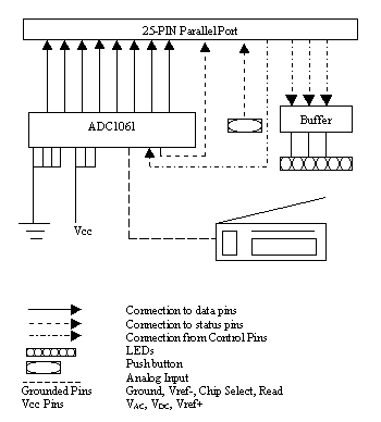
The device uses 14 pins of the parallel port to transmit and receive signals. 10 connections goes into the port, 8 from the data pins of the ADC, 1 from the end of convert pin of the ADC, and 1 from the status of the push button. 4 connections goes out of the parallel port, 1 going to the start convert pin of the ADC, and 3 going to the LED display.
Fig.2 Schematic Diagram of the Hardware
The analog audio signal, after passing through two filters, is passed to the input pin of the ADC.
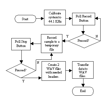
Fig. 3. Flow chart of Operation
As can be seen from the flowchart, the software controls the entire operation of the system, except for turning on the machine. It assumes that the ADC gets the required power to operate. If not, it can only send an error message to the user. The actions taken are quite straightforward: First, the system is calibrated to the desired frequency. This step is required to make the software compatible with different processor speeds. The record button is then polled, waiting for the signal to start recording. A debounce mechanism prevents the recording of samples less than 1 second in length. After recording, the data are transferred sample by sample to two WAV files, with pre-calculated headers already inserted.
Several trials using the project resulted in digital files that though not as crisp as the original signal, are still passable representations of the original sound. The samples blend well, signifying a good replication of a continuous analog signal. The main concern is the amount of noise that is not removed by the filter. The possible cause of this is the amplitude of the voltage coming from the source, which is only about 10% of the range the ADC circuit can convert. On a brighter note, the circuit could then be utilized to accept signals of higher voltage inputs without changing anything. The AM/FM radio could be replaced by other devices, as long as the new sources have headphone connectors on them. |


