STATUS MONITOR FOR AN AUTOMATED HOUSEJoey N. Costoya, Erees Queen B. Macabebe, Carla Verena S. Nuñez Abstract— To fully reap the benefits of an automated house, there is a need for a monitoring system to keep track of the status of each individual device and to control these from one computer. The Status Monitor is a program that provides a view of the house’s current settings and conditions. The information is acquired via a central computer that communicates with all other equipment and this data is translated to graphical and textual representations. The Status Monitor also allows the user to input new settings through the keyboard or through text message (SMS). The text message input is received as a file from a remote administration module that is also connected to the Status Monitor. These inputs are passed to the central computer, to be disseminated to other modules as a command to change their settings. All events received and transmitted by the Status Monitor are recorded in a text file. Index Terms—status monitor, automated house, central computer, remote administration
any simple households functions can be executed by electronic means, which can potentially aid reduce the amount of time and energy people spend on performing these tasks. Automation has long been implemented in factories and various work places, yet this affordable technology has yet to infiltrate the home.
This project was developed in tandem with the creation of electronic devices for an automated house. When there are many electronic tools used to perform the different functions within a house, it becomes more expedient for the user to keep track and control all of these devices from one monitor unit instead of having to go to each individual electronic unit to change settings or check for emergency conditions. An effective central monitoring system needs to integrate all of the important information regarding the state of the devices constituting the automated house, and then make this information accessible to the user. It is also ideal that the user is able to manipulate the settings of the devices from the same monitoring system, especially when emergency conditions arise. The status monitor project thus aims to achieve the following: 1) To provide the user a comprehensible graphical representation of the status of the house; 2) To take in user inputs through the keyboard/mouse or through a text message (SMS) to alter the current settings of the house; and 3) To record all the events within the house system. The status monitor is designed to reside within a central computer located within a designated control room of the house. 1) Software Component: The monitor system is mostly software that allows the central computer to communicate with other software modules that are in direct control of certain devices. The modules relay to the monitor system the necessary information regarding the settings of devices while the monitor system transmits user inputs to the concerned modules so the changes can take effect. 2) Hardware Component: The hardware included in the unit is a simple indicator and annunciator unit, which serves to call the user’s attention when any emergency conditions arise. The project was made for a one-semester course and in the context of a larger working system. The displayed settings were limited to the data acquired from the two modules created for the automated house project, which were the access/security module and the environment module. The same limitations applied to the available control options for the user. Visual C++ 6.0 was used to implement the software.
The program relies heavily on the communication links between the different modules of the automated house. The status monitor is linked to an interconnection module that takes care of the communication between the status monitor module and the modules controlling the devices in the house. The interconnection module polls each module. Data is communicated in the form of files: the status monitor sends command files to and receives status files from the interconnection module. A separate module that is connected directly to the status monitor module is the remote administration, which displays the settings of the house on the Internet and allows the user to view and control the settings of the house through a mobile phone. The remote administration module may request for a status file, which the status monitor grants by sending the most recent registered settings. The remote administration may also send a file containing user inputs to change settings, which is converted into a command file by the status monitor and sent to the interconnection module for dissemination to other modules.
Fig. 1. Interconnection of the modules in the AI House set-up
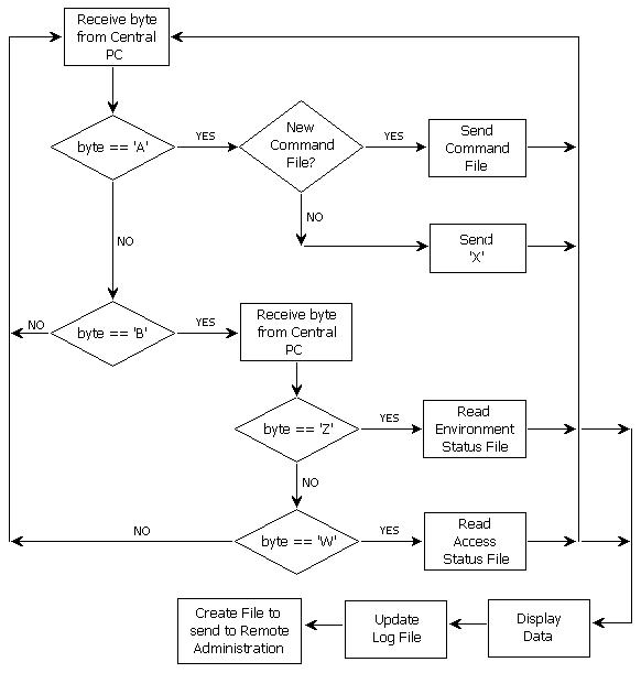
The flowchart of the program is outlined in Fig. 2. The protocol in sending and receiving files are illustrated in the first few blocks. Once the status monitor is addressed by the interconnection module pc, the program waits to receive the character ‘A’ or ‘B’. An ‘A’ prompts the status monitor to send a new command, if there is any waiting to be sent, otherwise an ‘X’ is sent to the interconnection module to specify that no new user inputs have been received. A ‘B’ received from the interconnection module indicates that new settings have been registered: if the next character received is a ‘Z’, then the data comes from the environment module; if a ‘W’ is received instead, then the data comes from the access/security module. When a new status file is received, the program updates the display, updates the log file, and creates a file to be sent to the remote administration module. The visible part of the program for the status monitor involves the user interface for display and input. These are the first to be updated by the program. The main display window presents the current status of the house and also allows the user to open a second window where inputs are accepted. A hardware component is also part of the display and is attached to the status monitor computer. This acts as an indicator and annunciator for emergencies.
Fig. 2. Flowchart of the program
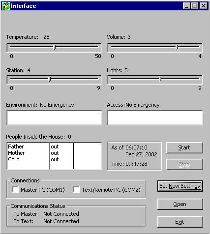
The generated display, shown in Fig. 2, is the first window the user encounters upon opening the status monitor program. The settings initially presented are the last values registered when the program was previously executed. These settings include the temperature, the brightness level of the lights, the radio station and volume, the emergency status of the environment and access/security modules, and the list of people currently inside the house. Also displayed are the current system time and date and the time of the last update. Several buttons on the window allow the user to set-up the system: a) Start opens the communication with other modules by simultaneously running a program (by implementing multithreading within the program) that manages port inputs and outputs. The user may choose to enable or disable connections to the interconnection modules and the remote administration using the checkboxes labeled master PC and remote administration PC, respectively. b) Stop halts communication with other modules and the display remains as it is. This option only becomes available when there is multithreading of programs, after the Start button has been pressed.
Fig. 3. The display window
c) Set New Settings directs the user to the window for input of new settings. d) Open is used to refresh the display with the settings of the status file. e) Exit quits the program.
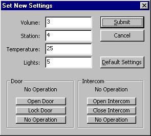
When the user clicks the Set New Settings button on the display window, the input window appears containing the modifiable fields for the environment module devices, which are the temperature, the brightness level of the lights, the radio station, and the radio volume. All the fields have values corresponding to the current settings.
Fig. 4. The window for input of new settings
There are also buttons that allow the user to close and open the door and the intercom, which are normally controlled by the access/security module. Fig. 3 shows the input window. When the Submit button is clicked, the modifications made to the settings are saved as a command file. The user also has the option to use the default settings, which sets the temperature to 25, the lights to 2, the radio station to 1, and the radio volume to 0. Opto-couplers, consisting of gallium arsenide infrared emitting diode and silicon phototransistor, are used to isolate the parallel port from the alarm unit, preventing current from flowing towards the parallel port in case of hardware failure. The CD4066 quad bilateral switch receives the signal from the opto-couplers. When the signal from the parallel port bit is active, the switch automatically closes allowing current to pass through the circuit. Otherwise, the switch is closed. The indicator circuits for the environment and access/security emergencies each composed of a 6V, 0.5 mA bulb, a 3.3kW resistor and two 2N2222 transistors to minimize the current going through the switch. The annunciator circuit, which is activated every time there is an emergency, produces a high frequency sound generated using a NE555 timer. Since the parallel port has latch up capabilities, it is necessary to inactivate the parallel port bits for the alarm to turn off by setting the bits to zero. After a new status file is received and the contents of the display window are refreshed, the program records the new settings in a log file. The log file contains the following entries: 1) Date and time of update; 2) Environmental settings – temperature, brightness of lights, radio station, radio volume; 3) Emergencies for the environmental and the access/security modules; 4) People who came in and went out of the house, including their time of entry or exit; and 5) People currently inside the house
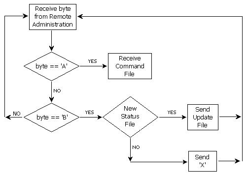
Fig. 5. Flowchart for communication with the text/remote access module The program proceeds to create a new file for the remote/access module in case a request for status update is received. Shown in Fig. 5 is the flowchart for the communication between the status monitor and the text/remote group. The status monitors waits until the port connected to the text/remote access computer receives the character ‘A’ or ‘B’. An ‘A’ indicates that a command file generated from user input through text message (SMS) will be sent. The status monitor receives this command file and then relays this to the interconnection module when it prompts for a new command. A ‘B’ would mean a request for an updated status of the house. The new file created by the status monitor is then sent. However, if no recent updates have occurred, the status monitor simply sends an ‘X’ to the text/remote access unit, which indicates that no changes have occurred since the last status update file sent.
The status monitor was able to properly function within the framework of the automated house, achieving the objectives of the project: events within the environment and access/security modules were displayed; the user was able to control using keyboard/mouse and text message several functions of devices within the houses; and events were recorded in a log file. The program needs to be expanded to include other devices that may be added to the automated house as well as include security measures to protect the system data. |