AUTOMATED HOUSE INTERCONNECTION MODULEMichael Loe Gestoso Fernandez, Eduardo Malco Gallofin, Jr. ABSTRACT The Automated House project provides a model for a house with components monitored and controlled through a network of computers. The model has five modules. The Access and Security, Environment Control modules are the monitor modules that monitor and control the conditions in the house. The Status Monitor/Control, Remote Administration are the control modules that allow the user to input instructions for the monitor modules. The Interconnection Module manages the communication among modules. All the computers that are performing specific tasks for the AI House are connected to the Central computer via their serial ports and communicate through a command file and a status file. The serial ports, which are designed for a "one-to-one" communication, are fitted with homemade hardware and software to convert them into a "one-to-many" / "many-to-one" configuration.
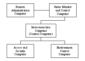
The Automated House has five modules, namely the Interconnection Module, the Status Monitor and Control Module, the Remote Administration Module, the Access and Security Module and the Environment Control Module. In brief, the Status Monitor and Control Module is the user’s interface to the control and status of the house. The Remote Administration Module allows the user to view and control the conditions of the house through their cellular phones (via SMS) and the Internet. The Access and Security Module provides the necessary identification and permission to the people entering the house. Lastly, the Environment Control Module controls the lights, temperature and radio in the house through voice-command. However, in order for the house to become fully functional, it must be able to coordinate the actions of the different modules. The Status Monitor and Control must be able to relay the commands or instructions to the corresponding module and be able to retrieve the status of the house for display. Thus, there is need to develop the process and technology to enable these modules to coordinate their actions and become a single integrated system. The general objective of the Interconnection Module is to develop and implement the means to coordinate the actions of the different modules, allowing the modules to function independently, while at the same time centralizing the control and monitoring of every module to a single master computer. The specific objectives of the Interconnection module are as follows: Based on the issues and objectives presented above, the following guidelines were followed to complete the project. Every module in the Automated House has a designated computer, allowing each to function on its own. Thus, the whole house has five working computers. All these computers are connected as illustrated below.
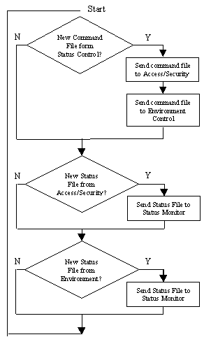
Figure 1 Network Topology of Module Computers The Status Monitor/Control, Access/Security and Environment Control computers are directly connected to the Central computer, and the Remote Administration computer is connected to the Status Monitor/Control computer. The Central computer controls the communication and flow of data among the computers connected to it. Figure 2 illustrates the procedure used by the central computer in arbitrating the communications among the computers. The computers communicate through a command file and a status file. The command file comes from the Status Module/Control. This file has a specific format containing the instructions to be executed by the Access/Security and Environment Control modules. The Access/Security and Environment Control modules generate a status file each. The file contains the recent conditions of the modules (i.e. temperature, persons entered) and is sent to the Status Monitor/Control to be displayed on the screen. The Central Computer controls the communication among the module computers by polling. First, it sends a signal to the Status Control/Monitor, asking for the command file. If there is a new command pending in the Status Control Computer, the command file is received by the central computer and is sent to the Access/Security and Environment module computers, to be executed. If
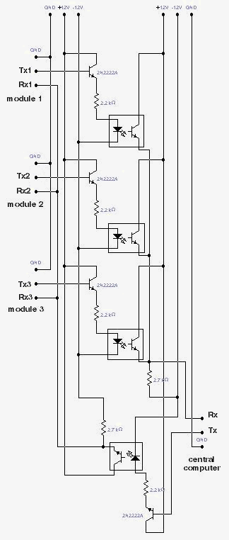
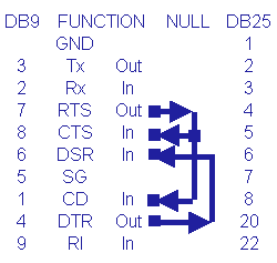
Figure 2 Polling process for the Central Computer there is no new command to be executed, no command file is received and the central computer proceeds with the next task. Next, the central computer polls the Access/Security computer, asking for a new status file. If there is a new status file, the central computer receives the file and sends this file to the Status Monitor/Control computer for display. If there is no new status, no status file is received and the central computer proceeds with the next task. The same process is done to the Environment Control computer. The central computer repeats the polling process by starting again with the Status Monitor/Control Computer. The hardware component of the interconnect module was primarily implemented with the use of the serial ports of the various modules through some opto-isolators. The reason for the use of the opto-isolators lies in the very nature of the communication protocol that the modules used. In a nutshell, the central computer broadcasts an address with certain commands to the three modules (the access/surveillance module, the environment control module, and the status monitor/control module). Each of those modules would have a specific reply format sent to the central computer in accordance to the accompanying address. What is needed is a hardware that can broadcast a command to the various modules and at the same time allows each module to respond only to the central computer. The serial ports, which are designed for a "one-to-one" communication, need to be fitted with some hardware to convert them into a "many-to-one" and/or "one-to-many" configuration. However, such hardware requirements may be implemented without the use of any opto-isolators. The implementation with opto-isolators provides more than just having a "many-to-one" and/or "one-to-many" configuration. It provides a safety precaution in order to protect the various interconnected computers from being destroyed due to some glitches in another’s system. The heart of any opto-isolator is to electrically separate two components from each other. Thus, if ever one connected computer suddenly changes its ground reference level, the other interconnected units may be protected from any damage. As a further option, the receive pins of the three other modules may also be fitted with opto-isolators to achieve full electrical isolation. Figure 3 gives you a schematic diagram of the "serial bus" that was implemented for the various modules to communicate with each other. What were used in the actual construction were four opto-isolators (4n25), four 2.2K resistors, two 2.7 K resistors, and four NPN transistors (2n2222A). Customized db9 cables, with some proper configurations for serial communications, were used as connections from the "serial bus" to the central computer and to the other modules. The voltage supplies used were +12V, and -12V to conform to the specification for voltage of the signals at the serial ports. In the actual implementation of the cable connections, the configuration for the cable connected from the serial bus to the central computer is different from the cables connected from the serial bus going to each of the modules. The cable connection coming from the central computer is configured as a db9 null modem cable. In this configuration, the computers are made to believe that a hand-shake has been established by shorting the output pin RTS with the input pins CTS and CD. Likewise, the output DTR is shorted with DSR. The Tx and Rx pins coming from the computer are also the Tx and Rx pins in the serial bus. Figure 4 is a graphical summary of the configuration of a null modem cable.
Figure 3. Schematic diagram of the "serial bus"
Figure 4. Configuration of a null modem cable. It will be seen that pins 2 and 3 (db9) of the cable connection coming from the central computer are the Rx and Tx connection of the serial bus respectively. The cable configuration coming from the three modules going to the serial bus are different in that pins 2 and 3 coming from the modules correspond to the Tx and Rx pins of the serial bus respectively. Instead of having a cable that has a direct connection between the pins (2 and 3) from the modules and going to the serial bus, as is the case with modems, these are interchanged so that Tx goes to Rx, and vice-versa. The configuration of the opto-isolator circuits is able to accomplish the connection of Tx to Rx. The reason for this rather non-uniformity of cable configuration is that before the serial bus was completed various tests were already performed to validate the effectivity of the software communication protocol. What was needed by then was a cable that has a switched connection between pins 2 and 3 from one end to pins 3 and 2 to the other end. It was rather a choice of having to conserve resources and time that instead of having to rewire the connections between the cables, the serial bus would perhaps have to adapt to the settings of the cable connections. However, in the real design of the serial bus, all that is need is actually a null modem cable, where all the computers OR their outputs. The switching of the pins which is the heart of serial communication is done internally between the circuitry of the serial bus. The programs used by the computers to communicate were written in VISUAL C++ v.6. There are two types of programs written: the Module Program and the Central Program. The Module Program, which runs in the background of the Access/Security and the Environment Control computers, receives the command file from and sends the status file to the Central Computer. The Status Monitor/Control has a main program with receive and send capabilities based on the Module Program. The Module Program constantly reads the serial port for new data and checks if it is being referred to by the Central Computer. If it is being referred to, it either receives a command file or sends a status file, depending on the byte ID sent to it by the Central computer.
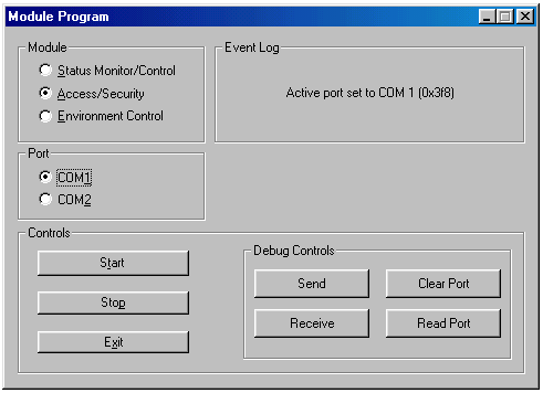
Figure 5. The user interface of the Module Program As shown in Figure 4, the Module Program has a number of controls allowing the user to select the corresponding module and the communications port to be used. Debug controls are also available for the user to easily check if the module is connected. An Event Log display allows the user to view the current status of the program. The Central Program runs in the Central Computer, and proceeds with the polling process as illustrated in Figure 2. It is able to send and receive files to and from the module computers.
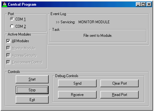
Figure 6. The user interface of the Central Program The interface of the Central Program is similar to the Module Program. It has a select option for the communications port, the modules connected to the Central Computer, Event Log of the current task being executed by the program, and debug controls to check the connections. The necessary hardware and software were developed and communication among the module computers was implemented. Commands from the Status Monitor and Control computer were sent to the different modules and were successfully executed. Also, the Status Monitor and Control was able to receive the status files of the different modules. One major concern with the implementation of the project was the numerous computers used in the system. This idea was reasonable, since with the given period of time to finish the project, the modules must be able to work independently and simultaneously with the different modules. Given its success, the project may serve as a model for the development of the project for a single computer system, making it more economical, reliable and easier to use.
|