ENVIRONMENT CONTROL THROUGH SPEECH RECOGNITIONMark de Guzman, Mark Bendicion, Antoine Bunnell, Sol Magsuci, Zorayda Marcojos, Ria Reyes
Abstract The environment module controls the intensity of the lights, the temperature of the air conditioner, and the volume and station of the radio, via speech command. Interfacing is made through the parallel port using C++ and speech control is processed through a MatLab program that sends control signals through an outputting function. Main processing is accomplished in MatLab and control signals are sent to the C++ functions using text files. Although speech command takes precedence, the system is also controlled through keyboard (PC) and via cellphone text messages. The lights and air conditioner are controlled by sending signals to an R-2R ladder circuit coupled with appropriate operational amplifier configurations. The light intensity and the temperature in the room are monitored through a light intensity detecting circuit and a temperature sensor connected to ADCs. Depending on the signals detected, a request for parameter change is sent to, processed and sent back by the computer to the requesting I/O. Radio volume is altered by digitally changing the input resistance of an operational amplifier circuit. The radio station is selected either by resetting the station to the start of the FM band or by scanning for the next FM band. Index Terms MatLab, speech recognition I. Introduction The first attempts of man in controlling machines have been marked by nuts and bolts connected by gears and belts to move big structures. With the birth of electrical devices, dials and switches have replaced these bulky structures in controlling smaller electrical devices. Thus the onset of electrical appliances offer customers the convenience of operating the instruments with just a click of a button. Then came the remote controls that allow users to control devices from afar by just pushing some buttons. With the fast-paced lifestyle that we have however consumers would certainly appreciate automated technologies that can be operated through voice -- that is, hands-free. Accordingly, speech recognition applications have recently become popular areas for research and development. In brief, speech recognition is the process of converting acoustic signals captured by a microphone, telephone or any receiver into a set of words [1]. Since speech recognition applications, especially those that do not apply isolated-word speech recognition, usually vary in terms of timing (being incapable of distinguishing words in a continuous speech -- resulting in a required pause between words), the researchers utilized the isolated-word speech recognition approach.
II. Statement of the Problem In the Philippines, prevalent control of devices has been limited to mechanical dials and remote controls. To make the technology of automation more available in the country, we desire to develop an economical, centralized control system that handles, by speech command, the physical, visual and aural components of an enclosed environment.
A. Objectives of the Study The project aims to automate the house by implementing a speech command software that recognizes eight distinct commands controlling the lights, air conditioner and radio inside the house. Signals from the voice command are obtained from the soundcard and are then processed through MatLab. The computer is then interfaced to the three appliances to act as a central module that will control the appliances. The parallel port is used for integration and appropriate circuits are added to the device enabling the computer to control the specified household appliances. B. Methodology The project can be divided into two parts namely signal processing and appliance control. Signal processing was implemented through a software program written in MatLab and the appliances are adjusted for interfacing by adding hardware circuits to the control switches of the appliances.
The software implementation can be divided into two parts namely signal processing and computer interfacing. The software for voice command processing is implemented through MatLab and can be divided into three parts namely command recording, normalization and signal processing [2 & 3]. The interfacing program is written in C++ and controls and monitors the house appliances by outputting appropriate signals through the parallel port. Ambient temperature and lighting conditions are likewise monitored by inputting signals from temperature and light sensors within the room.
The hardware implementation can be divided into six parts namely, the central interface circuit, the dimmer circuit, the light sensor circuit, the air-conditioner input and output (temperature sensor) circuits, and the radio control circuit. The central interface circuit serves as the bridge between the computer and the appliances, while the dimmer circuit, the air-conditioner input, and the radio control circuits take charge of manipulating the functions of the appliances. Lastly, the light sensor and the temperature sensor indicate the current light intensity and the temperature inside the room.
C. Scope and Limitations Control of the environment through voice command is limited to only three appliances namely, lights, air conditioner and radio. The user can choose among eight recognizable commands that control the devices. The light intensity can be increased, decreased or the light could be turned off through the commands brightness raise, brightness drop and brightness, respectively. The air conditioner can be turned on or off by saying hot or not hot, respectively. The radio volume can be increased or decreased through the commands radio raise and radio drop, respectively. The user is also given the option of scanning the radio station upward by saying radio. Command recognition however, can only be implemented among the built-in commands so that if a different word or phrase is voiced into the command, a possible error may occur if the value obtained from the user falls within the built-in commands. Control of the air conditioner is also limited to the turning on and off of the fan and compressor. To simplify control of the radio, the radio selected tuned only in the FM band (or mode), and it already had digital switches for tuning. III. Software Setup and Configuration A. Speech Recognition In implementing the speech recognition software for the module, MatLab Version 5.3 was used since it offers built-in functions for audio signal handling. In general, the software is designed to distinguish between eight sets of speech commands that may consist of one or two words. To make signal processing easier, the command is chopped into two parts and then processed separately. To implement this, the software consists of three methods namely recording, normalization and processing. In brief, recording ensures that all significant data in representing a speech command is obtained while the user says a command. The normalization then chops off noise at the beginning and end of the audio data and then expresses all data points relative to the mean of the signals gathered. Finally, the signals are transformed into a transfer function so that signals expressed in the time domain are compared. For the recording procedure, the built-in wavrecord function of MatLab is used. The length of recording period was set to ensure that only one word command is captured in the wave file to be analyzed. In our implementation, the length of recording is determined by trial and error. By first recording a particular command for a sufficient length of time, the time of recording is lessened gradually so that only the command is recorded in the wave file and that the silent segments in the audio file is minimized. Since the commands may contain one or two words, controlling the length of recording is important. Consequently, the command is dependent on timing so that a delay in the voicing of the command may cause an error in signal processing. Since silence and background noise may not be totally eliminated during recording, data from the wave file is normalized. A constant for acceptance is obtained by getting the sum of the mean of the signals and 15% of the maximum of the signals. Signals at the front and rear end of the file are then compared to this constant so that if they fall short of this value, they are chopped off from the signals to be processed. Such chopping off allows the program to filter the signals that are minimal and thus may be considered random noise. Thus another limitation set on the user is that the voice command should be said loudly so that the microphone can detect signals within the accepted magnitude and thus may be processed. In the case that no signal is left for processing, a warning of no input is displayed on the screen. If the signals obtained from the wave file are of acceptable value, the program proceeds in calculating the formants of the word or words spoken. Initially, the program employs an auto-regressive modeling formula which models the signals obtained from the wave file in terms of theta. Since comparison is based on amplitude graphed in the frequency domain so that primarily, the signals in theta are transformed into a frequency domain expression of the function using a transform function. Peaks are then obtained by comparing the signal under consideration with the two signals adjacent to it. If the signal is larger than the one it precedes and is at least equal to the one it follows, the signal is considered to be a peak and is retained for comparison. After obtaining formants for the wave file, the voice command is then identified by qualifying the value of the first formant obtained relative to the pre-determined formant range for the commands available in the module. After identifying the command, an appropriate 4-bit code is written in a text file, which is then sent to the interface program so that corresponding signals may be sent to the appliance under consideration.
B. Computer Interfacing Once the speech recognition software has performed its function, it is now time for handling of the given 4-bit code. In order to interface all the devices to the computer for the module, Borland C++ Version 3.0 was used since it offers simple, shared file reading as well as shared file writing procedures for ease of communication with the speech recognition software. Also, Borland C++ offers ease of access of the computer ports, including the parallel/printer port, which would be utilized for computer control over the three household devices, the lights, the air-conditioner, and the radio. In general, the software is designed to decode the encoded file written by the speech recognition software. The decoded command, which could be any of eight sets of speech commands, would then be implemented through a series of procedures, pertinent to the specific command. The computer interface software also takes commands from other computers, in the form of text files. Also, it writes status files containing all information about the room environment, like the current station playing on the radio, the volume of the radio, the intensity of the light, and the temperature of the room. Since there is a handful of operations being performed by the interface software, a proper sequence of events is necessary. First, a command from an external computer is read. If it is a new command, then it shall be performed; otherwise, the program would move on. Second, the speech command would be acknowledged. If there is a new command, then it shall be performed; otherwise, the program would move on. After these two procedures, the program would check if there were any new commands. If yes, then the readings from the sensors would be taken, and a status file would be written; otherwise, the program would loop back in search of a new command. For most of the commands, these steps are followed. However, if the air-conditioner were turned off, there would be a three-minute software delay before the air-conditioner could be turned on again. This is done to safe guard the compressor of the air-conditioner. This is implemented by a background timer, which is triggered once the compressor is turned off.
IV. Hardware Setup and Configuration A. Mode of Operation Since there are 25 pins available from the printer port, a greater amount of data could be transferred at one particular instant, making control over the household devices faster [4]. The 8 data pins are utilized for transfer of data with varying high and low bit combinations to drive the three specific devices. The 4 control pins are utilized for enabling four different LS373 latches, which in turn would handle four specific divisions. One latch is dedicated for light intensity control, another is dedicated for air-conditioner control, and another is dedicated for radio control, and lastly, a latch is dedicated for input signals coming from the light and temperature sensor. The 4 status pins are utilized for taking inputs from the temperature and light intensity sensors. Lastly, two additional pins are utilized to serve as the ground of the computer. B. General Description of the Circuits 1. Central Interface Circuit For the central interface circuit, opto-isolators were utilized for isolating the computer from the external devices (see Figure 1). In the 4N25, the photosensitive transistor prevents leakage current from entering and damaging the computer’s printer port and possibly the motherboard [5]. The light emitting diode in the 4N25 is activated by an external PNP transistor, 2N2907, at the lower voltage part of the circuit, activated by a printer port data pin. A logic LOW from the printer port causes the LED to light, and activate the corresponding light activated transistor, to give an external logic LOW. A logic HIGH from the printer port produces a zero voltage difference at the LED, causing it to emit little or no light, thus deactivating the corresponding light activated transistor, and giving an external logic HIGH. Since there are 8 data pins and 4 status pins, a total of 12 sets of the said device were assembled.
2. The Dimmer Circuit This is the part of the environment module responsible for the control of the lights. The computer sends a 4-bit signal to the light control circuit. This circuit is composed of the dimmer circuit and the digital to analog converter circuit. The dimmer circuit is composed of mainly of a capacitor, a variable resistor and a triac (see Figure 2). If the variable resistor is at its minimum setting, with almost zero resistance and the 220 Volt-AC voltage is applied, the capacitor will immediately start charging up. The breakdown voltage of the internal diac is reached in a very short time (almost negligible). The capacitor then discharges through the gate of the quadrac, which in turn triggers it ON thus connecting the lamp to the AC supply. Setting the variable resistor to an immediate value causes the capacitor to charge up slowly when the AC voltage is applied. This in turn causes a lapse from the time when the voltage is applied to the point when the quadrac conducts and puts the load across the line and as a result, the load lamp receives only the remaining voltage after the delay. Naturally, the load lamp then lights up less. The variable resistor charges the trigger time of the quadrac and therefore, indirectly controls the intensity of the load lamp. This circuit exhibits hysteresis, which means the turning off point is not the same as the turning on point. To reduce this to a negligible level, the 4 diodes and additional resistors are added (see Figure 3). The additional components also provide symmetrical triggering or firing angle of the quadrac. The inductor and the additional capacitor are added to suppress whatever static noise the circuit may generate. Since the controlling factor of the whole light control circuit is the voltage input from the computer, the variable resistor in the dimmer section of the circuit can be controlled through this input voltage. This is what the digital to analog circuit does by using a light dependent resistor (LDR) for the variable resistance [6]. The analog to digital converter circuit (see Figure 4) is composed of a solid-state switch, a CD4066 IC was used, and resistors in an R-2R (where R stands for the value of the resistors) ladder with an operational amplifier as shown in the figure [7]. The output of the op-amp is then connected to a light-emitting diode. The brightness of this LED shall vary depending on the digital input where each bit is equivalent to 5 Volts each. This brightness in turn controls the resistance of the LDR. The resistance of the LDR increases as the brightness it detects from the LED decreases and decreases as the brightness from the LED increases. The dimmer and the analog to digital circuits are not directly connected as the light from the LED are their only connection and therefore guarantees that the 220 V-AC voltage of the dimmer circuit will not affect the analog to digital circuit. Adjustments were also made in the R-2R ladder to acquire the desired resistance for the LDR.
Figure 2: General Dimmer Circuit
Figure 3: The Dimmer Circuit
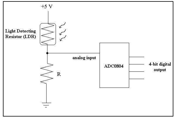
Figure 4: The Digital to Analog Circuit 3. Light Sensor Circuit The light detecting circuit determines the illumination in a specific room (see Figure 5). It measures the brightness or dimness of the room. The circuit is composed of a light-detecting resistor (LDR) connected in series with a resistor. The circuit is powered by a +5 Volt source. The intensity of the light inside the room is measured by taking the voltage across the light-detecting resistor. This voltage varies according to the intensity of light, since the LDR’s resistance varies inversely proportional to the intensity of light. The resistance of the LDR decreases as the room gets brighter and increases as the room gets darker. The analog voltage across the LDR is then converted to a 4-bit digital output using the analog to digital converter (ADC0804).
Figure 5: Light Sensor Circuit The 4-bit output is then sent to the interfacing software of the environment module. The different digital outputs mean different levels of brightness inside the room. Below is the summary of outputs and their corresponding meaning:
An output of 0000 means that the room has effectively no illumination while 1111 means that the room is very bright. 4. Air-conditioner Control Circuits The air-conditioner control part of the environment module, as the name suggests, is responsible for controlling the air conditioner. The circuit below represents the input part of the whole air-conditioner control system.
The LM35 sensor senses the temperature inside the room and converts this temperature to its respective voltage value (the LM35 has a linear +10mV per degree Celsius scale factor). This voltage then is amplified and sent to the ADC. The ADC digitizes the signal and sends it to the computer through the parallel port. The program the compares the temperature equivalent of the signal to the user-set temperature. If the sensed temperature (signal) is lower than the user-set temperature (room temperature is colder), the program sends an enable signal to the output and a disable signal if the sensed temperature is higher than the user-set temperature (room temperature is hotter). Below is the circuit for the output part of the air-conditioner control system. The relay here is an normally close relay, thus when an enable signal is sent the relay switches the air-conditioner off, and conversely, on a disable signal it switches the air-conditioner on.
5. Radio Control Circuit An ordinary FM radio – with switches for tuning control and a knob for power and volume control – was configured to be controllable by digital signals. This modified FM radio circuit was interfaced through latches and opto-isolators to a PC’s printer port, which sent out signals produced by the computer interface program. a. Modified Radio Power Source: Two AAA batteries originally powered the radio bought. To remove the need for batteries, the following voltage divider was constructed: 2 red light emitting diodes (LEDs) and a silicon diode were placed in series with a 1 kiloOhm (1/4 Watt) resistor. The current was limited by a total of 1.25 kiloOhm, external (outside the radio) resistance, which would give a current of 7.2 mA for a 9.0 V source, and 2.4 mA for a 3.0 V source. The reason for this calculation for a 9.0 V source is that the power source being used for the decoder circuit (providing the logical conversion of the input to the output), is measured to be 9 Volts (though the label says 6V) – in case the diode contacts were to deteriorate, the resulting voltage input to the radio should not result in a current that would destroy it. The 1.25 kiloOhm resistance comes from the 1 kiloOhm resistance between the 6V (9V when measured) source and the diodes, and the 250 ohm resistance was placed in between the radio and the 6V source (measured: 9V) ground (2 – 500 ohm resistors in parallel).
b. Solid-State Switches: CMOS solid-state switches were used in this module to configure the switches on the radio and to vary the gain of an amplifier circuit. The purpose of using a solid-state switch is to convert mechanically activated switches to digital-electronically activated switches. Since 4 solid-state switches are available in one package, on the other hand, there are 2 switches for tuning in the radio’s circuit, only 2 are left for volume control if only 1 4066 IC is to be used [8]. Power (voltage) to the radio would be activated directly by the decoding circuit. The 4066 Integrated Circuit (IC), has switches that are individually activated through enable pins, such that if the enable pin of a specific switch is fed a logic HIGH (5V), the switch conducts (low resistance); whereas, if the enable pin were fed a logic LOW (0V), the switch has comparatively high resistance. Resistors placed in parallel, the connections of which are controlled by the 4066 IC, provide a varied equivalent resistance controlled by the enable signals to the 4066 IC. Given 2 bits for volume control, there are 4 possible states (00, 01, 10, 11 Binary; or volume levels 0, 1, 2, 3, respectively). For input to be significant with volume level 0, an 80 kiloOhm resistor was placed directly from the unamplified audio output to a (1458N) amplifier’s inverting input. The resistors controlled by the 4066 IC were 120 and 40 kiloOhms, so that the equivalent resistances were 80, 48, 27 and 22 kiloOhms for volume levels 0, 1, 2 and 3, respectively. D-flip-flops were used to retain the volume levels. c. Decoding for Selective Activation: This radio module has a total of 4 input bits, which can be named E, A, B and C. E is connected to the D-flip-flop’s clock enable; A is decoded to select volume control (HIGH) or tuning control (LOW); B controls the Tuning "Scan" switch, if A is LOW; C controls the Tuning "Reset" switch, if A is LOW; and if A is HIGH, BC is latched onto the D-flip-flop to give the volume level. "Scan" means search forward in the FM band for the next radio station, and "Reset" means return to the beginning (or the lowest receivable frequency) in the FM band.
Transition Diagram/Truth Table: *Although there are many possible transitions and combinations, these are the inputs recommended for reliable control
X - "DON’T CARE" (0, 1, transition from 0 to 1, transition from 1 to 0) T - Transition (start from 1, transition to 0, transition back to 1) 0 - 0 Volts 1 - Above 3 Volts (but less than 9 Volts) "DO NOTHING" - Remain at the present tuning and volume level
d. Tuning Control: It was possible to control the "SCAN" and "RESET" switches using the circuit attached to the radio. Thus when "SCAN" was activated, different stations were heard; and when "RESET" was activated, the first receivable station in the FM band (89.1 MHz) was detected. When the "RESET" switch is activated, a noise is heard (similar to static, or scratching) that is not heard when the "SCAN" switch is activated separately. The source of this noise is unknown. e. Volume Control: It was also possible to control the volume level using digital signals according to the inputs at EABC. However, the volume difference between levels does not sound linear: there seems to be no audible difference between volume level 0 and volume level 1, while there is an obvious (certainly audible) difference between volume level 2 and volume level 3. This likely arises from non-linear function of the op-amp; or it may arise from the non-linear relationship between voltage and audibility (proportional to power).
V. Conclusion With the current trend in automation, the project has demonstrated control of household appliances through speech command. Using the computer as the central coordinator, it is possible to process voice commands and output appropriate signals that will activate and manipulate devices inside the house. The project was implemented through software and hardware. The software involved signal processing and interfacing to the devices.
The environment controls the pervading mood of a room. Enabling the user to set the lights, air-conditioner and radio with the convenience of just saying a command increases the adaptability of the environment to the lifestyle and present mood of the user. Being able to set the parameters of devices within the room is one step in being able to totally control an enclosed area’s artificial environment / atmosphere, via a centralized environment control system. This may be a small advance in communication systems – but this is the beginning in the computer controlled monitoring of household communities.
Reference [1] http://cslu.cse.ogi.edu/HLTsurvey/ch1node4.html. 3 Sept. 2002. [2] Atun, Jose Rey and Fernando Pedregosa. Automatic Voice Recognition System. Ateneo de Manila University, 1990. [3] Amil, Nashieba, Alexis Artes, Willy Custodio and Federico Condes. Voice-Controlled Hospital Bed. Ateneo de Manila University, 2001. [4] Oppus, Carlos M. Computer Interfacing Via the Parallel Port. (PowerPoint presentation and lecture) Ateneo de Manila University, 2002. [5] www.thcal.com [6] http://alds.stts.edu/APPNOTE/Opto/photdiod.pdf [7] http://www.play-hookey.com/analog/d2a_converter.html [8] www.fairchildsemi.com/pf/CD/CD4066BC.html
|