LIGHT-CONTROLLED CAR
(Toy Car with Light Dependent Resistor)
back to projects page
Raymond Ong, Tanya Gabe, Jaeyoun Kim
- Introduction
We tried to make a toy car which could change its course to all directions without bumping in the given track that has a lightened boarder. We used LDR (Light Dependent Resistor) for light sensing switch which turned the motor of toy car.
- Materials
- Bread Board
 Light Dependent Resistor (LDR): It decreases its resistance when light falls on it. The resistance of LDR varies according to the amount of light that falls on it. A typical example is the ORP 12 type which will vary its resistance from about 2 Mega ohms in the dark to 100 ohms in normal room lighting. The light-sensitive part of the LDR is a wavy track of cadmium sulphide. Light energy triggers the release of extra charge carriers in this material, so that its resistance falls as the level of illumination increases.
- Transistor: 2N2222 (NPN) and 2N2907 (PNP)
- Diode: It is a component that allows current to flow in only one direction. It has a positive side and a negative side. When the voltage on the positive leg is higher than the negative leg then current flows through the diode (the resistance is very low). When the voltage is lower on the positive leg than on the negative leg then the current does not flow (the resistance is very high). The positive leg of a diode is the one with the line closest to it.
- DC Motor
- NE555 Timer IC
- Resistors
- Circuit Diagram
- Sensor Part
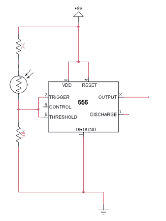
We connected the LDR to the 555 IC to detect the Logic ‘0’ and ‘1’. If the surrounding of the LDR is dark, the resistance of the LDR goes very high. So, the voltage of the LDR node becomes lower than 1/3 of the voltage source. So, the output will be Logic ‘1’. On the other hand, if the surrounding is bright, the resistance of the LDR becomes low, the voltage of the LDR node is higher than 2/3 of the voltage source. That makes the output (pin 3) of 555 IC to Logic ‘0’. After that, we connected the pin 3 of 555 IC to the motor part of our circuit
- Motor Part
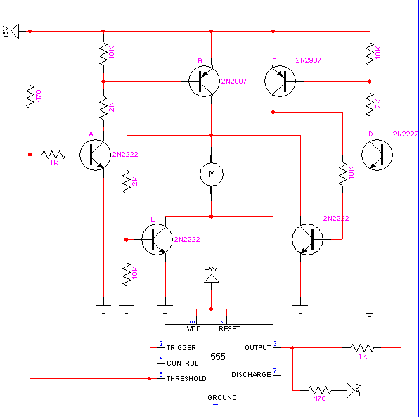
We connected the pin 3 of 555 IC of the sensor part circuit to this motor circuit. The motor part is the combination of the inverter circuits with many transistors. We kept changing the logic of the circuit. Eventually, we were able to control the motor.
The toy car initially moves forward or when the surrounding is dark. But when the LDR senses a light, the toy car reverses. The transistors, which act as inverters, are responsible for the forward and backward motion of the car. When the second circuit (circuit as shown above) detects logic "1" from pin 3 of 555 IC, Transistor A would invert it and output logic "0" from its collector. Transistor B would detect that logic "0" and invert it into logic "1." Transistor E detects this logic "1" and inverts it into logic "0." So when the surrounding is dark or the LDR detects no light, this set of outputs makes the motor run forward. The upper part of the motor (as shown in the diagram above) detects logic "1" of the collector of the Transistor B. The lower part of the motor detects the logic "0" of the collector of Transistor E.
As for the reverse part, another 555 IC is attached to the motor part of the circuit to ensure that the output of pin 3 of the first 555 IC and the collector of Transistor D will never have the same value. Otherwise, it will produce disastrous results. The 555 IC inverts the output of pin 3 of the other 555 IC (the first 555 IC). The motor will reverse only when the surrounding is bright or when the LDR detects bright light. When the LDR detects bright light, Transistor D would detect logic "1" from pin 3 of the 555 IC, and invert it into logic "0." Transistor C would then invert it into logic "1." Transistor F detects logic "1" from the collector of Transistor C, and then inverts it to logic "0." Logic "1" of Transistor C would proceed to the lower part of the motor, while logic "1" of Transistor F would proceed to the upper part. This makes the motor reverse.
- Discussion
- LDR Part
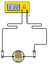
First of all, we tested LDR to see its characteristics on how it changes its resistance. The resistance of LDR varies according to the amount of light that falls on it. In darkness, its resistance is much higher than that of LDR in brightness.
- Transistor and Motor Part
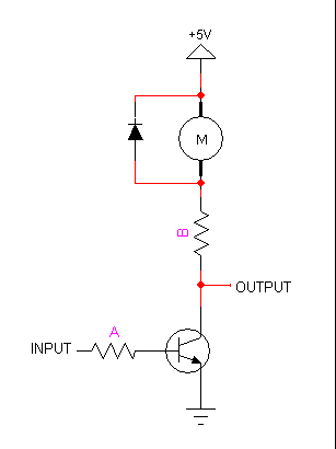
We connected a transistor to control the motor. To activate the transistor, we had to supply a minimum voltage to its base. When a light falls on the LDR, the resistance of the LDR is low so that the voltage on the base of the transistor is not sufficient to drive it into conduction. When we darkened LDR, the resistance of the LDR increased. So, the potential at the base of the transistor was raised. The resulting increase in the current flow at the base of the transistor amplified at the collector of the transistor to turn the motor on. Moreover, when the transistor is off, no current flows through the transistor.
- Inverter
To run the motor either clockwise or counterclockwise, we built the inverter circuit with the transistor. So, the output of the inverter is the opposite of the input.
|
Input |
Output |
|
1 (5 volts) |
0 (0 volts) |
|
0 (0 volts) |
1 (5 volts) |
(Basic Inverter Circuit)
If the input is 5 volts (Logic 1), the output will be 0 volts (Logic 0) so that the motor will run. However, if the input is 0 volts, the output will be 5 volts. Therefore, the motor might not run. We used several transistors to control the direction of the motor.
- Diode
We connected the diode to the DC motor to prevent the destruction of our circuit due to the back voltage or counter electromotive force (EMF).
- Conclusion
During our final experiment, we learned how to amplify the current and how does the inverter circuit work.
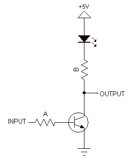
If the transistor is on, then the Base voltage is 0.6 volts higher than the Emitter voltage.
If the transistor is on, the Collector voltage is 0.2 volts higher than the Emitter voltage.
|
For example, if the resistor A and B are 10k and 1k respectively, the current flowing through the A resistor is (5V - 0.7V) / 10000 ohm = 0.00043 A = 0.43 mA. The current flowing through the B resistor is (3.6 - 0.2) / 1000 = 0.0034 A = 3.4 mA. Therefore, the current flowing through the B resistor is higher than that of the resistor A. That means we can amplify the current by using of the transistor.
If we want more current flowing through the DC motor, we can use a smaller resistor for the resistor B, and we will get more current through the DC motor without changing the amount of current that comes from the input. This means we can control a DC motor that consumes lots of power with a low power circuit. We can turn transistors on and off even with small current, and that is enough to control lots of current for DC motor.
Unfortunately, we could not build a real toy car with our circuit. However, this experiment was a good chance to learn about the sensor (LDR) and the applications of the transistor.