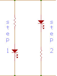
A. What purpose do the resistors have in the Step 1 & Step 2 diagrams?
In the Step 1 and Step 2 diagrams, both resistors have the same purpose. Their purpose is to decrease the current passing through the circuit to the Light Emitting Diode (LED) since the LED will only light if the current passing through it is equal to 10 milliamps or less. The presence of the resistors is very important in order to light up the LED. The LED operate on around 1.2 volts, and a resistor is very important to placed in series with the LED to limit its flow of current and to prevent it from burning. A 380 W or greater resistor makes sure that the current will not exceed 10 milliamps because of Ohm's Law of I = V/R.
Computation:
V = IR à by Ohm's Law
R = V / I
R = (Ground voltage - Voltage drop across LED) / 10 mA
R = (5 V - 1.2 V) / 0.01 A
R = 3.8 V / 0.01 A
R = 380 ohms

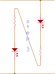
B. How do you recognize 1's and 0's using the circuit you built in Step 3? Give a brief explanation.

We can recognize 1's and 0's from the circuit in Step 3 by connecting the probe to either the ground or the +5 and determining which LED lights up. When the probe is connected to the ground, the LED for logic "0" or the "low" lights up. This is the LED nearer to the +5. When the probe is connected to the +5, the LED for logic "1" or the "high" lights up. This is the LED nearer the ground. This happens since "1's" are between 2.4 and 5.0 volts while "0's" are between 0 and 0.8 volts.
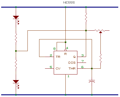
C. What is the purpose of the capacitor and resistor to control the speed of the change from "1" and "0" in the diagram. Give a brief explanation.
The capacitor and the resistor are important parts of the circuit to be able to control the speed of the change from "1" and "0". The amount of resistance from the resistors will determine how much current will pass through to the capacitor to charge it. The capacitor then acts as storage for this current. The 555 IC will then act as an oscillator, switching form high to low, depending on the voltage from the capacitor. So, the amount of current passing through the circuit and how fast the capacitor charges and discharges will determine the speed of the change from "1" and "0" and these factors are controlled by the resistors and the capacitor. This explains why a potentiometer connected to the resistors will allow us to control the speed of blinking of the LED's of "1" and "0".
D. How does the 555 run an "oscillator"? Give a brief explanation.

As mentioned earlier, the 555 IC will act as an oscillator. The 555 will switch from "1" and "0" as shown by the blinking of the LED's. The 555 can do this with the help of a capacitor connected to pin 2 (trigger) and to pin 6 (threshold). As the capacitor charges and discharges, these two pins check how much voltage passes through. When the voltage reaches 1/3 of the voltage in the circuit, pin 2 will tell pin 3 to go high and the capacitor begins to charge. When the voltage reaches 2/3 of the voltage in the circuit, pin 6 will tell pin 3 to go low and the capacitor starts to discharge. Since the probe is connected to pin 3, when pin 3 goes high, the LED for high lights up and when it goes low, the LED for low lights up. This cycle goes on and on with the capacitor alternately charging and discharging.
|