Ian Clarito
Bien Theodore D Felix
Aquilino Gamban
Patrick Philip R Sanchez
This device alarms you if the light coming from the laser pointer is interrupted or blocked-off. This can be used to create a perimeter alarm to warn you if someone is near the object you’re protecting (parang Mission Impossible, hi-tech!!!).
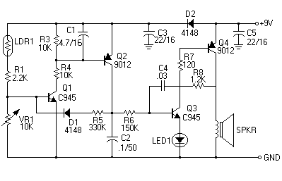
As we were thinking of how to do this project, one of our group mates unexpectedly found a circuit that is similar to what we needed – a Light Activated Alarm:
Operation:
A sensor, switching circuit, and an oscillator comprise the whole circuitry. Q1 and Q2 constitute the switching section while Q3 and Q4 form an oscillator circuit to produce a sound once triggered. LDR1, other known as a photocell, acts as the sensor. The LDR has a normally very high resistance. When the light strikes the LDR, its resistance goes down to a very low vale. In the circuit, LDR1 is wired in series with R1 connected as a voltage divider in conjunction with R2 and VR1 which sets the bias to the base of Q1. VR1 sets the sensitivity, when light strikes LDR1, its resistance goes down to a certain value approximately setting the proper biasing of the base of Q1 thus triggering it to conduction. When Q1 conducts, Q2 is triggered into conduction then successively triggers Q3 and Q4 to conduct whereby producing an oscillation which is then fed to the speaker, LED1 lights simultaneously as the alarm sounds.
Assembly:
Insert and solder all components carefully following the parts placement guide on the PCB starting from the smallest ones on to the next larger and so on. Carefully observe proper placement of parts specially the polarized ones. Cut all excess leads neatly to avoid possible shorts that could cause failure in your work.
Testing:
Apply power to the kit with a 9-volt battery. The alarm will sound off as the LDR is exposed to light. If no sound is emitted, adjust V1 to a point just enough to set n the alarm. Cover the LDR. The sound of the alarm should be off and sets on again as you uncover the LDR. To establish directivity in the light sensing, conceal the LDR in a tube.
LIGHT ACTIVATED ALARM PARTS LIST
TRANSISTOR C945 2
C9012 2
DIODE 1N4148 2
CAPACITOR
ELECT 22/16 2
4.7/16 1
0.1/16 1
CER .03 pF 1
RESISTOR 2.2K 1
10K 2
330K 1
150K 1
1.2K 1
120 Ohms 1
TRIMMER RESISTOR 10K 1
LED JUMBO RED 1
LDR (PHOTO CELL) 1
SPEAKER 0.25W, 8 Ohms, 2" 1
PCB
STRANDED WIRE
BATTERY CLIP for 9V 1
BATTERY 9V 1
SLIDING SWITCH 1

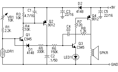
Since the function that we need for our project is the reverse of what the original circuit does, we needed to implement a few changes. These are the modifications that we implemented to the circuit above – the Laser Light Burglar Alarm:
- The main determinant for triggering of the alarm is the LDR. Therefore, we had to switch the positions of the Variable Resistor and the LDR. In this configuration, the resistance of the LDR has to be greater than that of the VR and R1 combined, for the proper biasing of the base of Q1 to occur. This means that a light source has to be pointed directly to the LDR so that the resistance in that part of the circuit is low. A laser pointer is the ideal light source for this application. Now, if the light source is blocked, Q1 is triggered causing the alarm to sound off.
- We also placed another LED in parallel to LED1 because the sound that is produced by the circuit was not very pleasant. This configuration draws more current therefore the capacitor, C4, charges and discharges faster. This in turn, causes faster oscillation so that the speaker produces a louder, higher-pitched sound.
- A switch for the power source was integrated.
- We also designed a switching circuit to enable us to switch the device function from Burglar Alarm to Light Detector, and vice versa, at will.

