INTRODUCTION
Often times, students are not able to recognize the process and concepts behind the colorful play of lights they love to watch during the Christmas season. The running lights and the colors may have successfully covered the basics of electronics, but it has also opened the eyes of the watcher to the wonder that should be learned and explored.
MATERIALS USED
1) logic board
2) light emitting diodes (2 two)
3) power supply (5 volts)
4) resistors (2 two)
5) capacitor
6) NE 555 IC
7) Potentiometer
8) Stranded wire
9) Wire stripper
SCHEMATIC DIAGRAM


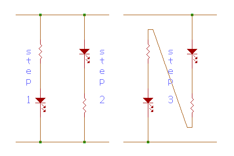
A. What purpose do the resistors have in the Step 1 & Step 2 diagrams?
The resistor in step 1 and step 2 is used to limit the current passing through the light emitting diode (LED). This is done so that the LED is not overloaded. The voltage across the probe is 5 volts while the current is about 10 mA. A LED will light up with a voltage of 1-1.2 volts. If a 380 W resistor is connected in series with the LED, 3.8 volts will go across this resistor while only 1.2 volts will go across the LED, just enough to operate it without burning it out.
B. How do you recognize 1's and 0's using the circuit you built in Step 3? Give a brief explanation.
Step 3 is called a logic probe. A logic probe is used to recognize 1's and 0's. A voltage in the low range is considered to be a logic 0 and a voltage in the high range is a logic 1. When the probe is at logic 0, the top LED will light up. At logic 1, on the other hand, the other LED will light up. Thus, we are able to identify the 1's and 0's.
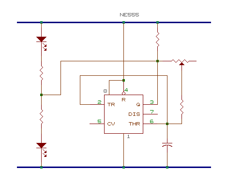
C. What is the purpose of the capacitor and resistor to control the speed of the change from "1" and "0" in the diagram. Give a brief explanation.
The capacitor, in combination with the resistor acts as a timer. This happens because when the resistance of the potentiometer (resistor) is low, the current is high which allows the capacitor to fill up much faster. When the resistance is high, the current is low which delays the time the time for the capacitor to fill up. This is how the capacitor along with a variable resistor controls the speed of the change from 1 to 0 in the circuit.
D. How does the 555 run an "oscillator"? Give a brief explanation.
The circuit with the NE 555 IC is called an oscillator. Voltage between pins 4 and 8 (VCC) of the 555 is divided into three. Whenever pin 2 goes below 1/3 of the supply voltage, it signals pin 3 to go high and the output at pin 7 is high impedance or non-conducting. Whenever pin 6 goes higher than 2/3 of the voltage, pin 3 is at low and and pin 7 is at low impedance or conducting. With the 1 kW connected to pin 3 then to VCC, current charges the capacitor through the two resistors.
|