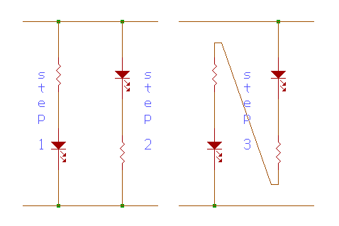
A. What purpose do the resistors have in the Step 1 & Step 2 diagrams?

The light-emitting diodes (LED's) can handle only a relatively low current. In steps 1 and 2 of the diagram above, the presence of the 470O resistors simply ensures that the current that passes through each of the LED's does not exceed the maximum of 10 milliamps.
B. How do you recognize 1's and 0's using the circuit you built in Step 3? Give a brief explanation.

In step 3 of the diagram above, 0's and 1's are represented by the higher LED and lower LED, correspondingly. At logic zero, the current passes through the higher LED and through the 470O resistor, and the probe (as step 3 of the diagram is called) will show a lighted higher LED and an unlighted or very dim lower LED. On the other hand, at logic one, the current passes through the other 470O resistor and through the lower LED. At this point, the probe reveals a lighted lower LED and an unlighted or very dim higher LED.
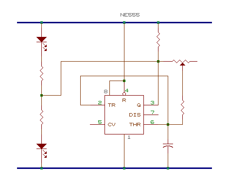
C. What is the purpose of the capacitor and resistor to control the speed of the change from "1" and "0" in the diagram. Give a brief explanation.
In the diagram above, the capacitor-resistor combination serves as a timer for regulating the change from 1 to 0.
The capacitor can be likened to a container that stores charges. With such a container, in order for charges to be "flushed out" through the connections of the circuit, the container / capacitor must first be filled up. Just as with any container, the faster the capacitor charges up (or the greater the current that passes through it), the quicker or shorter the time interval for it to flush out.
The resistor serves as a means for controlling the current that flows through the capacitor. Hence, the speed of the "flushing out" can be controlled by varying the resistors used. Moreover, using a special kind of resistor called a potentiometer (a resistor that allows one to increase or decrease the resistance at the turn of a dial), one can smoothly control and change the speed by very small increments.
D. How does the 555 run an "oscillator"? Give a brief explanation.
The 555 runs as an oscillator by being a "timer" in changing the flow of current through the circuit. It changes from high to low and back to high again, then back to low again, depending on each input and output.
|