Definition of Terms
Electric Circuit - an interconnection of electrical elements such as resistors, capacitors, integrated circuits, etc.
Resistor - a device used to control current in an electric circuit by providing resistance.
Capacitor - a device that stores electric energy in the form of an electric charge.
Voltage Source - source of electromotive force or potential dofference.
A. What purpose do the resistors have in the Step 1 & Step 2 diagrams?
In the circuit, the resistors in Step 1 and Step 2 are supposed to limit the voltage to 5 Volts so the light emitting diodes next to them would not acquire too much voltage and go off.
B. How do you recognize 1's and 0's using the circuit you built in Step 3? Give a brief explanation.
In Step 3, we had a probe attached between two LEDs. When the probe was connected to the +5 volts, the Logic 1 (high) LED lit up. When it was connected to the ground, the Logic 0 (low) LED lit up.
C. What is the purpose of the capacitor and resistor to control the speed of the change from "1" and "0" in the diagram. Give a brief explanation.
For the purpose of the experiment, the capacitor was used as a timer. When the potentiometer (a resistor) was at a high level, it used up more voltage thus, the capacitor receives less voltage and it takes longer to be filled with energy. Likewise, when the potentiometer is at a low level, more voltage would go directly to the capacitor.
When the capacitor is fully charged, it releases all its stored energy then waits until it is fully charged again. This cycle results in a "blinking" flow of electricity. When the resistance is high, the capacitor charges slowly so the "blinking" is slow. When the resistance is low, the capacitor charges quickly so the "blinking" is fast.
D. How does the 555 run an "oscillator"? Give a brief explanation.
A timing capacitor is used in the circuit. It starts out with no voltage and is fed current from a voltage source. Pin no. 2 and pin no. 6 of the NE555 chip are then connected to the capacitor. When pin 6 senses that the voltage in the capacitor reaches two-thirds Vcc, pin 3 of the 555 will return low, and the capacitor starts to discharge to zero. Now when pin 2 senses that the voltage reaches one-third Vcc, pin 3 will return high, and the capacitor starts to charge up again. The charge/discharge cycle repeats over and over giving us a repetitive waveform or an oscillation.
|
|
Part A - Describe what you saw in this experiment.
After we finished setting up the circuit, the LED's lit up in succession. With the use of the potentiometer, we were able to adjust the rate at which the LED's lit up. Decreasing the resistance in the potentiometer increased the rate at which the LED's lit up in succession while increasing the resistance did otherwise.
Also, several IC's were connected to each other to make the lights run in sequence. These IC's were also connected in the circuit to alter the behaviors of the lights. By playing with the 1's and 0's that enter in each IC, we were able to control what sequence of the LED's we want.
Part B - Operating the 7490 counter.
a. How did you connect the input pins 14 and 1?
Pin 14 was connected to the signal source NE555. Pin 1 was connected to pin 12 because pin 12 is the output for the 1st stage.
b. Where did you connect them? Why?
Input pin 14 is connected to NE555 while input pin 1 is connected to the output pin 12. Because pin 14 is connected to signal source, pin 14 can either be 0 or 1. Because pin 1 is connected to the output pin 12, it takes alternating values of 0 and 1 at the fastest possible rate.
c. Which are the output pins? Where did you connect them?
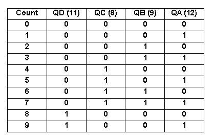
The output pins are the pins 11, 8, 9, and 12. We connected them to the input pins 12, 13, 14, and 15 of the 7442 decoder respectively.
d. What are the functions of pins 2 and 3?
Pins 2 and 3 (R01 and R02) are grounded. They are output pins that reset the counter back to zero. When pins 2 and 3 are high, A = "0"; B = "0"; C = "0"; D = "0"; thus the IC 7490 creates an output of "0000" that makes the counter reset to 0.
e. What are the functions of pins 6 and 7?
Pins 6 and 7 (R91 and R92) are also grounded. They are also output pins that reset the counter back to nine. When pins 6 and 7 are high, A = "1"; B = "0"; C = "0"; D = "1"; thus the IC 7490 creates an output of "1001" that makes the counter reset to 9.
f. Draw a table that expresses the relationship of the output pins as the 7490 counts from "0" to "9".

Part C - Operating the 7442 decoder.
a. What did you see when you connected the 7442 to the 7490?
We saw the 10 LED's which were connected to the output pins of the 7442 light up in sequence. It lit up the LED's connected from pin 1 all the way to pin 11, excluding pin 8. When 7442 was connected to 7490, the circuit makes the lights run in a sequence.
b. How did you connect the pins of the 7442 to those of the 7490?
We connected pin 12,13,14, and 15 of the 7442 to pin 11, 8, 9, and 12 of the 7490, respectively. The outputs of 7442 become inputs of 7490.
c. Why did you connect LED's to the output pins of the 7442?
We connected LED's to the output pins of the 7442 to see the result of the counting done by the 7490 Decade Counter.
|
|
Laboratory Report 3 - Making Decisions (Logic Gates / Selectors / Multiplexer / Demultiplexer)
TOP
back to PS141B
|
Part A. Give a brief description of the "black box" decoder that you built.
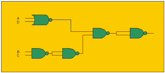
The black box is composed of two IC’s: 7400 and 7402.
Input pin A is connected to pin 3 of the 7402. Input pin B is connected to pin 1 of the 7400. Input pin C is connected to pin 2 of 7400. Input pin D is connected to pin 2 of the 7402.
Output would be pin 8 of the 7400. It returns “true” if and only if the input pins are 0110.
Part B. In your own words, briefly describe the operation of your black box.
Output pins B and C are NANDed. The output is split in two and then NANDed again.
Output pins A and D are NORed. The output of A and D and the final output of B and C are NANDed two more times.

The whole operation would return “true” if and only if the input pins are 0110.
Part C. How did you connect your black box to the 7490?
Output pins B and C of the 7490 is connected to pins 1 and 2 of the 7400 respectively. While output pins A and D of the 7490 is connected to pins 2 and 3 of the 7402 respectively.
Part D. Describe briefly what happened.
Only 6 of the 10 LED’s lit up in sequence instead of all the 10. And it’s not like it pauses after the 6th LED lights up. The 4 remaining LED’s are totally disregarded and the 1st LED lights up again right after the 6th.
|
|
|