Individual Narrative of Each Member
Mark Anthony Bendicion
Mark Percival de Guzman
Ria Adelle Reyes
The circuit is designed to be a game pattern where the player is tasked to reproduce the light pattern output using switches. Correct input from the player causes a corresponding LED to light so that a correct set of inputs from the player reproduces the light pattern.
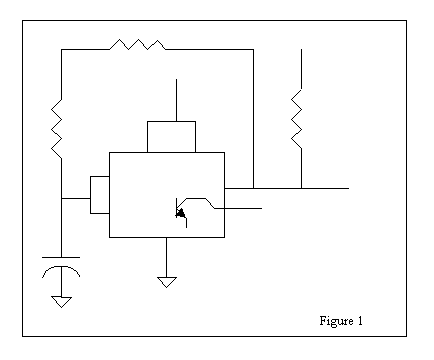
The initial task in the circuit was to produce a series of high and low signals that would correspond to lit and unlit LEDís. This was performed by producing clock signals according to the following diagram:

The logic of the sequential high and low output in the TTL lies in the alternating charging and discharging of the capacitor. Initially, the output at pin3 charges the capacitor causing a low output. After charging to a certain extent pins 2 and 6 detects a corresponding voltage level which would signal the 555 to lower its pin 3 output. This would subsequently stop the charging of the capacitor and the capacitor would now act as a voltage source. A reverse in current direction would now be observed and a corresponding high output at pin 3 occurs. Thus the alternating charging and discharging of the capacitor causes a corresponding cycle of low and high TTL outputs. From the diagram, it can be seen that the gap between high and low outputs depend on the duration of charging for the capacitor. The higher the capacitance, the longer the charging time and the longer the gap between and high and low outputs. Accordingly, different clock pulse patterns where employed in the circuit by producing 4 clock setups of varying capacitor value (as in Fig 1).
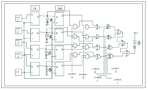
Accordingly, the signals are each connected in a series of D flip-flops. In particular, a signal passes through two D flip-flops. The series of flip-flops allows a series of light signals, which the user must reproduce.

The path through the D flip-flops provides a delay mechanism that allows a constant supply of output signals that would cause different light patterns to be reproduced in the game. The first set of flip-flops provides memory allocation for the next signals to be reproduced by the player. The second set of flip-flops on the other hand is where the signals are untapped and compared with the input of the player. Accordingly, the playerís input may be compared with either the first or second set of signals so that two signal data for each light is 'OR'ed. The resulting set of tapped signals are then compared to the corresponding inputs of the player using an XOR gate where a correct input would yield a low output. To utilize the low signal corresponding to a correct input, LEDís in forward bias are connected to the XOR output and the voltage source so that a correct input from the player would cause the LED to light.
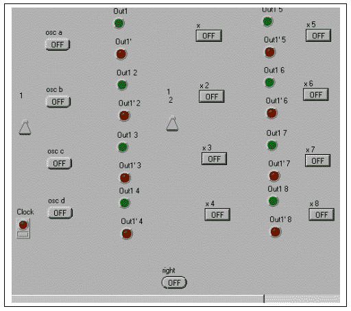
Before putting together the actual circuit, the logic of the circuit was first tested using LabView. However, the implementation of the circuit in this software was combinatorial rather than sequential because of technical problems encountered in using the software. Anyhow, the logic of the circuit worked and so the group proceeded in wiring the circuit.


One of the first problems encountered during troubleshooting was the turning off of the voltage source when connected to the circuit. The group suspected that this was due to a short along the circuit. Accordingly, two capacitors were detected to be connected to the source rather than grounded. These capacitors when connected to the ground may serve as output source for the clock when fully charged as well as a drain of current during low output. Perhaps, the connection of the capacitor to a source rather than to ground caused a continuous pulse of high outputs which rendered the clock not useful and the circuit paralyzed at the onset of its functioning
Aside from this, a wire was determined to be cut which rendered one of the LEDís useless. Such discontinuity along the wiring was determined by tracing the path of that particular LED. By linking different nodes on the breadboard with a separate wire, the functioning of that LED was monitored. It turned out that one of the wires was cut at an edge so that there was discontinuity in the circuit.
MECHANICS OF THE GAME
The main objective of the game is for the player to reproduce the light pattern using switches. However an added twist is added to the game. The player may be prompted to reproduce either the current or previous pattern depending on the mode indicated by two lights. If light1 is on, the current light pattern is to be reproduced. If light2 is on, the previous pattern is to be reproduced. If both lights are on, a combination of the current and previous pattern is to be inputted by the player. A correct input would be indicated by another lit LED.
ELC 111 / Ch174.1 — February 21, 2002
Individual Narratives of Learnings and Insights
TOP
Mark Anthony Bendicion
Ria Adelle Reyes
Mark Percival de Guzman
Mark Bendicion
I learned, through, making this digital memory game, that...
- You can use lines that control a set of data so that they select which data set is used.
- Delays changing data at the clock positive edge, when placed in series and their clocks are connected, the input data is obtained first before the output is changed. This makes the situation so that it is not necessary to sequentially pulse the clocks of the delays to shift the data from one delay to another.
- ICs which have delay circuits are available:74LS74. (We thought at first we had to make them from NANDs)
- Labview does not readily support sequential circuits involving flip-flops. Some data had to be manually changed for the sequential part of the circuit to store data.
- Clocks have to be made from 555's, resistors, capacitors and wires.(I thought they were compact ICs before.) Within the 555 are comparators, a set-reset flip-flop, a transistor, and resistors. The output is taken from the SR flip-flop, which is controlled by the comparators to which may be attached, externally, and RC circuit where the source is the output from the SR flip-flop. If the output is high, the capacitor in the external RC circuit is gradually charged. But the voltage from the capacitor is fed into the comparators that detect the voltage as it increases. When the capacitor voltage has reached logic 1, the comparator resets the SR flip-flop, giving a low output voltage and resulting in the gradual discharge of the capacitor. When the capacitor voltage has reached logic 0, the comparator sets the flip-flop giving an output of logic 1, resuming the cycle. Of course, in the beginning, the voltage at the capacitor is logic 0, and thus the flip-flop is initially set to logic 1.
- An initially ambitious project can be cut down to manageable size (from 4 sets of 4 delays to 2 sets of 4 delays, from automatic comparison to manual, from automatic scoring to manual scoring, etc.)
- I can buy many electronics materials from Alexan in SM North EDSA.
- It is possible to strip wires using a blade.
- Simple parts of projects that are done can be extended to make the project more complex as a whole bit-by-bit.
- It is more difficult to work with others on a project, but it is necessary since friends can stimulate thinking. ("Two heads are better than one.") Marvy helped me make up the design, while Ria helped me learn to explain it.
- Diodes have to be placed the right way for them to work. Initially the comparison LED turned on but was not oscillating, and the other LEDs were not lighting up -- we found that the LEDs were placed with the wrong polarity. We found that the larger electrode inside the casing of the red LED is the side that should be connected to the negative, for the LED to be positively biased. (So the next time the LED doesn't light as expected, I should check the polarity.)
- When all the lights came on and went off at the same time, we thought the oscillators were too similar to have different frequencies, but I knew I varied the capacitances, and the resistances, and we found I had connected the delay input to the clock along with the LED instead of the different oscillators.
- If an output has to be inverted to be the source on an LED, the output may be left un-inverted and instead connect the LED to the voltage source and let the output be the ground.
- Marvy is really good at identifying patterns...
- Where a data output becomes constant despite the logic demanding it to vary, I should check the connections to see if some connection has been broken.
- There are many ways to solve a problem. The more automatic a system is, while there are fewer inputs and outputs, more things can go wrong within the program since the whole has to be coordinated more and the data has to be generated within. (I learned this from my other classmates with more complicated projects.)
- Shorter wires can make a breadboard program look simpler as well as the arrangement of the components; while blockage over ICs by wires should be avoided to ease removing them in case any of them are damaged.
- Making something that works can be very rewarding. In other words, it can give one a good feeling of accomplishment.
- Things can be easier when you're really interested.
- Without practice, what is learned only conceptually can make little sense, or can be caught up in confusion over a single variable.(Remember #2?)
- Switches "bounce" and cannot be directly used as clocks, unless they are buffered (but I haven't learned to make one yet).
Ria Reyes
- Helping out in the LabView implementation of the circuit primarily helped me understand the significance of feedback in flip-flops. Since our knowledge in using the software was limited to implementing combinatorial circuits, we had to manually change the signals along the feedback line. Initially, we failed to change the corresponding feedback of the D flip-flop after an input of data so that the circuit didnít work. After detecting this lapse in the circuit, the significance of feedback in sequential circuit was better appreciated.
- When the circuit was designed, shift registers were not yet discussed in class. It turned out that the use of D flipflops in series was the logic behind the shift register IC. From this I realized that ICís are indeed convenient combinations of logic gates which implement systematically certain tasks depending on the design. This realization made ICs less intimidating for me since it made me realize that they are not at all that different from simple logic gates. All that is needed is an understanding of the design within the black box which makes life easier and more manageable.
- I also learned to see a breadboard with its components not as a clutter of pieces but rather as a highway of current. Initially, the clutter of wires and pins were very intimidating for me. After familiarizing myself with pin numbers and breadboard lines however, it was easier to understand the logic behind the connections. I was even able to detect two capacitors that were wrongly connected to a voltage source which perhaps contributed to the early failure of the circuit.
- I learned that ICís alone are not sufficient in implementing a certain task. I had the misconception before that ICís in themselves could facilitate current flow and that only wires are to be connected to the pins. Contrarily, I found out that they are usually coupled with resistors and capacitors to fully utilize their potential. I was even struck by how such components play a significant role in implementing certain functions. The type of capacitor used with the 555 for instance affected the pulsing of the signals.
- In troubleshooting, I learned that one of the most basic steps is to trace the lines and wiring which may cause a discontinuity along the circuit that would render some parts useless. We did this when one of the LEDís included in the light pattern did not function well. By using a separate wire to connect two points of connection, we traced the path of that LED and monitored whether connecting the wire would cause the LED to light. Indeed one of the wires had a cut end which isolated the LED from the rest of the circuit.
Mark Percival O. de Guzman
The entire ELC 111 project brought about a lot of insights and broadened my horizons with respect to what is really in store for us in the technological world. I never knew that there could be so much done with simple gates and logical devices. Also, with these simplistic devices, bigger and more complicated devices could be built. However, even though the logic devices become more and more complicated, they do not necessarily mean or lead to larger chips or set-ups. these logic devices could be reduced and implemented using different approaches and use of other simpler devices.
- I learned that from basic logic devices such as the NAND, AND, OR, and NOT gates, more complicated digital devices could be built or assembled such as DECODERS, ENCODERS, MULTIPLEXERS, FLIP-FLOPS, COUNTERS, etc., through digital design.
- From the combinations of these simple and complicated devices, much more complicated and integral circuitry could be assembled in the further enhancement of human activity in the society. Certain machines such as vendo-machines could be implemented using the combinations of these digital devices.
- In addition to these, logic devices could not only be utilized in combinatorial circuits. They could also be utilized in sequential circuitry, as represented by devices such as FLIP-FLOPS, COUNTERS.
- We learned that electronic games are actually built upon the concepts of simple logic devices.
- From our project, we tried to utilize a D-flip-flop. By using the D-flip-flop as a memory element, we were able to compare data that has already been inputted earlier to new data that was just recently inputted.
- We also learned that our project could have also been implemented using counters and shift registers, instead of mere flip-flops. However, due to time constraints, we decided to go on with our present implementation even though the present implementation would prove to be longer and more tedious than by implementing it using counters an shift registers.
- By utilizing a 555 as an oscillator, we were able to randomize the inputs that we deemed necessary for the game.
- Also, by using different and variable resistors and capacitors, we were able to change the outputs from the 555ís, thus generating 4 independent values/data at given time intervals (which is controlled by another oscillator).
- We also learned that there are a lot of ways to implement circuits. Thus, state minimization/reduction is needed in order to save time and money. Through this, unnecessary chips and devices may be removed from the entire circuitry. As an example, we previously designed the circuit with a NOT and an AND gate at the end for the final output. However, instead of using this approach, we removed the NOT and AND gates and replaced them with an OR gate, which we connected to a diode which was reversed biased for our output. Thus, instead of the diode lighting at a 1-logic, it lights up at a 0-logic.
- Also, as an aid to further understanding and state reduction, certain softwares have already been created, such as LabVIEWTM and WorkbenchTM.
- The most important learning that I realized in our project is that working together as a team has its ups and downs. However, by sticking together and not leaving someone behind, the project could be accomplished and completed, though it may seem problematic. that is why I am really proud of our group, from struggling it out and never giving up until the project was completed. Indeed, three heads are better than one.
TOP