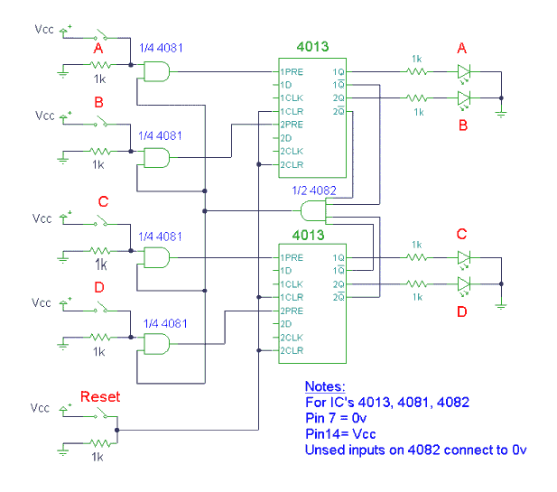
Circuit Description
This circuit design is a quiz show buzzer. In this circuit there are five inputs. Four inputs will be for the contestants A, B, C and D, which will be the switches that will be pressed by four persons. The first person that presses his input switch will light his corresponding output LED and disable the other inputs. The last input is the reset switch that resets the circuit.
Circuit Operation
The circuit we made utilized TTL’s (7474) in place of the CMOS IC packages. The first contestant to press his button locks out the other two contestants. The design is completely asynchronous and "fair".
Pressing the reset switch resets all flip-flops and switches off any lit LEDs. In this condition the Q outputs will register a low signal (logic 0) and NOT Q outputs will register a high signal (logic 1). The four NOT Q outputs will go into a 4 input AND gate. The output of the AND gate is connected to one input of each 2 input AND gate. The switch inputs, A<B<C<D are designed to be non latching input switches, hence the first contestant to press the switch will make the corresponding AND gate to go high, triggering the input of the D flip-flop. This in turn will latch and light the LED. The NOT Q output changes the AND gate output to low and thus locks out the other flip-flops. Pressing the reset button backtracks the circuit to its former state.

TOP